VPWS Accessing VPLS
L2VPN PWs have different encapsulation types, such as Ethernet and VLAN. These encapsulation types are essentially irrelevant to services. A service can be transmitted over VPWS and VPLS PWs in succession so long as these PWs use the same encapsulation type.
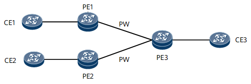
VPWS Accessing VPLS in Basic Mode
On the network shown in Figure 1, CE1, CE2, and CE3 belong to a broadcast domain. CE1 and CE2 are required to communicate only with CE3. To avoid imposing heavy pressure on the capacities of MAC address tables on PE1 and PE2, you can deploy a VPWS PW from PE1 to PE3 and from PE2 to PE3 to carry traffic from CE1 and CE2 respectively, and deploy a VPLS PW from PE3 to PE1 and from PE3 to PE2 to carry traffic from CE3.

Because VPLS uses split horizon by default, after PE3 receives traffic from CE1 and CE2, it does not forward the traffic over VPLS PWs back to PE1 or PE2. This implementation ensures that CE1 and CE2 can communicate with only CE3. If you want the three CEs to communicate with each other, change the VPLS PW attributes on PE3 to spoke.
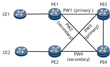
VPWS Accessing VPLS in Dual-homed mode
- If PE1 and PE2 use LDP VPWS, configure master/slave PW redundancy.
- If PE1 and PE2 use static VPWS, configure PW APS.
PW APS applies only to the NetEngine 8000 F1A.
After receiving traffic from CE1, PE1 forwards the traffic to PE3 over PW1. Upon receipt, PE3 broadcasts the traffic to PE2 and PE4 (because a VPLS network is a broadcast domain by default). Because the PW between PE2 and PE3 is a primary PW, PE2 can successfully receive the broadcast traffic and forward the traffic to CE2.