PBB VPLS Application
The deployment roadmap is as follows:
Before deploying PBB VPLS, complete the following tasks:
- Configure an IGP on the backbone network to ensure IP connectivity.
- Configure MPLS and MPLS LDP and establish LDP sessions.
- Enable MPLS L2VPN to ensure that the MPLS network can transparently transmit Layer 2 user data.
Deploy PBB VPLS to solve the scalability problem of the VPLS network:
- Configure B-VSIs, specify peers, and configure B-SMAC addresses.
- Configure I-VSIs and I-Tags, bind AC interfaces to I-VSIs, and configure B-DMAC addresses.
- To improve the reliability of PBB VPLS networks, you can configure
different reliability features for different network layers to implement
protection switching for links:
- Configure E-Trunk to implement link redundancy. If the primary link fails, traffic switches to the secondary link for transmission. To implement rapid traffic switching, the new master device will send LDP MAC Withdraw packets carrying PBB TLV, B-SMAC, and I-Tag information during a master/backup switchover.
- Configure VRRP, BFD, and PW redundancy to implement rapid traffic switching when a link fails.
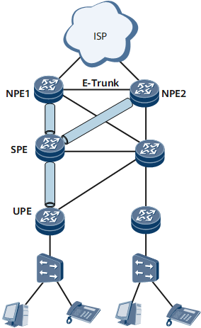
PBB VPLS in E-Trunk Scenarios
Residential service
On the network shown in Figure 1, an Internet service provider (ISP) network is dual-homed to two network provider edges (NPEs), and an E-Trunk is configured between the two NPEs to determine the master/backup status of NPEs. After the E-Trunk detects a fault on the primary link, the E-Trunk sends an LACP packet to the ISP network, instructing the ISP network to switch traffic to the secondary link. Meanwhile, the new master NPE sends MAC Withdraw messages to SPEs, instructing SPEs to delete B-MAC addresses.
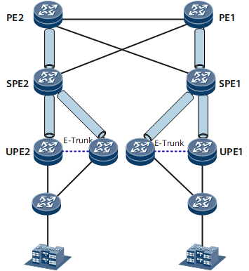
Enterprise service
On the network shown in Figure 2, enterprise devices attached to switches are dual-homed to UPEs. An E-Trunk is configured between each pair of UPEs to determine the master/backup status of UPEs. After an E-Trunk detects a fault on the primary link, the E-Trunk sends an LACP packet to the enterprise devices, instructing these devices to switch traffic to the secondary link. Meanwhile, the master UPE sends MAC Withdraw messages to SPEs, instructing SPEs to delete B-MAC addresses.
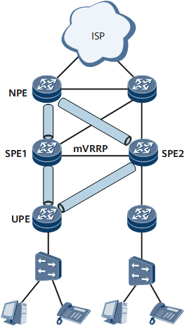
PBB VPLS in VRRP Scenarios
On the network shown in Figure 3, a UPE is dual-homed to SPEs over primary and secondary VPLS PWs. A Management Virtual Router Redundancy Protocol (mVRRP) backup group is configured on the SPEs and a management VSI (mVSI) is configured on the UPE. The mVSI is associated with multiple service VSIs. Link and peer BFD sessions are configured to track the mVRRP group. If a master/backup mVRRP switchover occurs, the new master SPE sends gratuitous Address Resolution Protocol (ARP) packets to the UPE. After receiving the packets, the UPE converts unicast traffic in all service VSIs associated with the mVSI to multicast traffic. The return traffic carrying a label mapped to the previous secondary PW is unicast traffic and traverses the new primary PW.