BGP-LS
BGP-link state (LS) enables BGP to report topology information collected by IGPs to the upper-layer controller.
Background
BGP-LS is a new method of collecting topology information.
- The controller must have high computing capabilities and support the IGP and its algorithm.
- The controller cannot obtain complete information about the inter-IGP area topology and so it cannot compute E2E optimal paths.
- The controller receives topology information from different routing protocols, making it difficult for the controller to analyze and process such information.
For details on how OSPF collects topology information, see NetEngine 8000 F Feature Description - OSPF.
For details on how IS-IS collects topology information, see NetEngine 8000 F Feature Description - IS-IS.
- Lowers the requirements on the controller's computing and IGP capabilities.
- Facilitates path selection and computation on the controller by using BGP to summarize topology information in each process or AS and report the complete information directly to the controller.
- Requires only one routing protocol (BGP) to report information about the entire network's topology to the controller.
Related Concepts
BGP-LS provides a simple and efficient method of collecting topology information.
BGP-LS routes carry topology information and are classified into six types of routes that carry node, link, route prefix, IPv6 route prefix, SRv6 SID, and TE Policy information, respectively. These routes work together to transmit topology information.
BGP-LS Routes
Based on BGP, BGP-LS introduces a series of new Network Layer Reachability Information (NLRI) attributes to carry information about links, nodes, and IPv4/IPv6 prefixes. Such new NLRIs are called Link-State NLRIs. BGP-LS includes the MP_REACH_NLRI or MP_UNREACH_NLRI attribute in BGP Update messages to carry Link-State NLRIs.
BGP-LS defines the following types of Link-State NLRI:
- Node NLRI
- Link NLRI
- IPv4 Topology Prefix NLRI
- IPv6 Topology Prefix NLRI
In addition, the BGP-LS attribute is defined for Link-State NLRI to carry link, node, and IPv4/IPv6 prefix parameters and attributes. The BGP-LS attribute is defined as a set of Type, Length, Value (TLV) triplets and carried with Link-State NLRI attributes in BGP-LS messages. All these attributes are optional, non-transitive BGP attributes, including Node Attribute, Link Attribute, and Prefix Attribute.
Node NLRI format
      0                   1                   2                   3
      0 1 2 3 4 5 6 7 8 9 0 1 2 3 4 5 6 7 8 9 0 1 2 3 4 5 6 7 8 9 0 1
     +-+-+-+-+-+-+-+-+
     |  Protocol-ID  |
     +-+-+-+-+-+-+-+-+-+-+-+-+-+-+-+-+-+-+-+-+-+-+-+-+-+-+-+-+-+-+-+-+
     |                           Identifier                          |
     |                            (64 bits)                          |
     +-+-+-+-+-+-+-+-+-+-+-+-+-+-+-+-+-+-+-+-+-+-+-+-+-+-+-+-+-+-+-+-+
     //                Local Node Descriptors (variable)            //
     +-+-+-+-+-+-+-+-+-+-+-+-+-+-+-+-+-+-+-+-+-+-+-+-+-+-+-+-+-+-+-+-+
Field |
Length |
Description |
|---|---|---|
Protocol-ID |
1 octet |
Protocol identifier, identifying a protocol such as IS-IS, OSPF, or BGP. |
Identifier |
8 octets |
Uniquely identifies a protocol instance when IS-IS or OSPF multi-instance is running. |
Local Node Descriptors |
Variable |
The Local Node Descriptors TLV contains Node Descriptors for the local node of the link. This TLV consists of a series of Node Descriptor sub-TLVs. |
Link NLRI format
      0                   1                   2                   3
      0 1 2 3 4 5 6 7 8 9 0 1 2 3 4 5 6 7 8 9 0 1 2 3 4 5 6 7 8 9 0 1
     +-+-+-+-+-+-+-+-+
     |  Protocol-ID  |
     +-+-+-+-+-+-+-+-+-+-+-+-+-+-+-+-+-+-+-+-+-+-+-+-+-+-+-+-+-+-+-+-+
     |                           Identifier                          |
     |                            (64 bits)                          |
     +-+-+-+-+-+-+-+-+-+-+-+-+-+-+-+-+-+-+-+-+-+-+-+-+-+-+-+-+-+-+-+-+
     //               Local Node Descriptors (variable)             //
     +-+-+-+-+-+-+-+-+-+-+-+-+-+-+-+-+-+-+-+-+-+-+-+-+-+-+-+-+-+-+-+-+
     //               Remote Node Descriptors (variable)            //
     +-+-+-+-+-+-+-+-+-+-+-+-+-+-+-+-+-+-+-+-+-+-+-+-+-+-+-+-+-+-+-+-+
     //                  Link Descriptors (variable)                //
     +-+-+-+-+-+-+-+-+-+-+-+-+-+-+-+-+-+-+-+-+-+-+-+-+-+-+-+-+-+-+-+-+
Field |
Length |
Description |
|---|---|---|
Protocol-ID |
1 octet |
Protocol identifier, identifying a protocol such as IS-IS, OSPF, or BGP. |
Identifier |
8 octets |
Uniquely identifies a protocol instance when IS-IS or OSPF multi-instance is running. |
Local Node Descriptors |
Variable |
The Local Node Descriptors TLV contains Node Descriptors for the local node of the link. This TLV consists of a series of Node Descriptor sub-TLVs. |
Remote Node Descriptors |
Variable |
The Remote Node Descriptors TLV contains Node Descriptors for the remote node of the link. |
Link Descriptors |
Variable |
The Link Descriptors field is a set of TLV triplets. This field uniquely identifies a link among multiple parallel links between a pair of devices. |
IPv4/IPv6 Topology Prefix NLRI
      0                   1                   2                   3
      0 1 2 3 4 5 6 7 8 9 0 1 2 3 4 5 6 7 8 9 0 1 2 3 4 5 6 7 8 9 0 1
     +-+-+-+-+-+-+-+-+
     |  Protocol-ID  |
     +-+-+-+-+-+-+-+-+-+-+-+-+-+-+-+-+-+-+-+-+-+-+-+-+-+-+-+-+-+-+-+-+
     |                           Identifier                          |
     |                            (64 bits)                          |
     +-+-+-+-+-+-+-+-+-+-+-+-+-+-+-+-+-+-+-+-+-+-+-+-+-+-+-+-+-+-+-+-+
     //              Local Node Descriptors (variable)              //
     +-+-+-+-+-+-+-+-+-+-+-+-+-+-+-+-+-+-+-+-+-+-+-+-+-+-+-+-+-+-+-+-+
     //                Prefix Descriptors (variable)                //
     +-+-+-+-+-+-+-+-+-+-+-+-+-+-+-+-+-+-+-+-+-+-+-+-+-+-+-+-+-+-+-+-+
Field |
Length |
Description |
|---|---|---|
Protocol-ID |
1 octet |
Protocol identifier, identifying a protocol such as IS-IS, OSPF, or BGP. |
Identifier |
8 octets |
Uniquely identifies a protocol instance when IS-IS or OSPF multi-instance is running. |
Local Node Descriptors |
Variable |
The Local Node Descriptors TLV contains Node Descriptors for the local node of the link. This TLV consists of a series of Node Descriptor sub-TLVs. |
Prefix Descriptors |
Variable |
The Prefix Descriptors field is a set of TLV triplets. This field uniquely identifies a prefix originated by a node. |
BGP-LS Route Formats
Format of node routes
For example, a node route is in the format of [NODE][ISIS-LEVEL-1][IDENTIFIER0][LOCAL[as100][bgp-ls-identifier10.1.1.2][ospf-area-id0.0.0.0][igp-router-id0000.0000.0001.00]].
Node routes carry node information.
Table 4 describes the fields in node routes.
Item |
Description |
|---|---|
NODE |
Field indicating that the BGP-LS route is a node route. |
ISIS-LEVEL-1 |
Protocol that collects topology information. The protocol is IS-IS in this example. |
IDENTIFIER0 |
BGP-LS identifier of the protocol that collects topology information. |
LOCAL |
Field indicating information of a local node. |
as |
BGP-LS domain AS number. |
bgp-ls-identifier |
BGP-LS domain ID. |
ospf-area-id |
OSPF area ID. |
igp-router-id |
IGP router ID, generated by the IGP that collects topology information. The router ID is obtained from the NET of an IS-IS process in this example. |
Format of link routes
For example, a link route is in the format of [LINK][ISIS-LEVEL-1][IDENTIFIER0][LOCAL[as255.255][bgp-ls-identifier192.168.102.4][ospf-area-id0.0.0.0][igp-router-id0000.0000.0002.01]][REMOTE[as255.255][bgp-ls-identifier192.168.102.4][ospf-area-id0.0.0.0][igp-router-id0000.0000.0002.00]][LINK[if-address0.0.0.0][peer-address0.0.0.0][if-address::][peer-address::][mt-id0]].
Link routes carry information about links between devices.
Table 5 describes the fields in link routes.
Item |
Description |
|---|---|
LINK |
Field indicating that the BGP-LS route is a link route. |
ISIS-LEVEL-1 |
Protocol that collects topology information. The protocol is IS-IS in this example. |
IDENTIFIER0 |
BGP-LS identifier of the protocol that collects topology information. |
LOCAL |
Field indicating information of a local node. |
as |
BGP-LS domain AS number. |
bgp-ls-identifier |
BGP-LS domain ID. |
ospf-area-id |
OSPF area ID. |
igp-router-id |
IGP router ID, generated by the IGP that collects topology information. The router ID is obtained from the NET of an IS-IS process in this example. |
REMOTE |
Field indicating information of a remote node. |
if-address |
IP address of the local interface. |
peer-address |
IP address of the remote interface. |
mt-id |
ID of the topology to which an IGP interface is bound. |
Format of prefix routes
For example, a prefix route is in the format of [IPV4-PREFIX][ISIS-LEVEL-1][IDENTIFIER0][LOCAL[as100][bgp-ls-identifier192.168.102.3][ospf-area-id0.0.0.0][igp-router-id0000.0000.0001.00]][PREFIX[mt-id0][ospf-route-type0][prefix192.168.102.0/24]].
Prefix routes carry information about reachable network segments.
Table 6 describes the fields in prefix routes.
Item |
Description |
|---|---|
IPV4-PREFIX |
Field that indicates an IPv4 prefix route. Prefix routes are classified as IPv4 prefix routes or IPv6 prefix routes. The router cannot generate IPv6 prefix routes, but it can process the IPv6 prefix routes received from non-Huawei devices. |
ISIS-LEVEL-1 |
Protocol that collects topology information. The protocol is IS-IS in this example. |
IDENTIFIER0 |
BGP-LS identifier of the protocol that collects topology information. |
LOCAL |
Field indicating information of a local node. |
as |
BGP-LS domain AS number. |
bgp-ls-identifier |
BGP-LS domain ID. |
ospf-area-id |
OSPF area ID. |
igp-router-id |
IGP router ID, generated by the IGP that collects topology information. The router ID is obtained from the NET of an IS-IS process in this example. |
PREFIX |
Field indicating an IGP route. |
mt-id |
ID of the topology to which an IGP interface is bound. |
ospf-route-type |
OSPF route type:
|
prefix |
Prefix of an IGP route. |
Format of TE Policy routes
For example, a TE Policy route is in the format of [TEPOLICY][SEGMENT-ROUTING][IDENTIFIER0][LOCAL[as100][bgp-ls-identifier1.1.1.1][bgp-router-id1.1.1.2][ipv4-router-id1.1.1.9][ipv6-router-id::]][TE[protocol-origin3][Flag0][endpoint2.2.2.2][color123][originator-as0][originator-address0.0.0.0][discriminator500]].
TE Policy routes carry information about SR TE Policy-related topology and status.
Table 7 describes the fields in TE Policy routes.
Item |
Description |
|---|---|
TEPOLICY |
Field indicating that the BGP-LS route is a TE Policy route. |
SEGMENT-ROUTING |
Segment routing. |
IDENTIFIER0 |
BGP-LS identifier of the protocol that collects topology information. |
LOCAL |
Field indicating information of a local node. |
as |
BGP-LS domain AS number. |
bgp-ls-identifier |
BGP-LS domain ID. |
bgp-router-id |
BGP router ID. |
ipv4-router-id |
IPv4 router ID. |
ipv6-router-id |
IPv6 router ID. |
TE |
Traffic engineering. |
protocol-origin2 |
Protocol origin of the primary path over an SR-MPLS TE Policy tunnel. |
Flag |
Flag bit. |
endpoint |
Destination IP address of an SR-MPLS TE Policy tunnel. |
color |
Color attribute carried in SR-MPLS TE Policy routes. |
originator-as |
Originator AS number configured for the primary path over an SR-MPLS TE Policy tunnel. |
originator-address |
Originator address configured for the primary path over an SR-MPLS TE Policy tunnel. |
discriminator |
Discriminator of the primary path over an SR-MPLS TE Policy tunnel. |
Format of IPv6 prefix routes
For example, an IPv6 prefix route is in the format of [IPV6-PREFIX][ISIS-LEVEL-2][IDENTIFIER100][LOCAL[as200][bgp-ls-identifier192.168.11.11][ospf-area-id0.0.0.0][igp-router-id0000.0000.0004.00]][PREFIX[mt-id0][ospf-route-type0][prefix4::4/128]].
IPv6 prefix routes carry information about reachable network segments.
Table 8 describes the fields in IPv6 prefix routes.
Item |
Description |
|---|---|
IPV6-PREFIX |
Field that indicates an IPv6 prefix route. Prefix routes are classified as IPv4 prefix routes or IPv6 prefix routes. The router cannot generate IPv6 prefix routes, but it can process the IPv6 prefix routes received from non-Huawei devices. |
ISIS-LEVEL-2 |
Protocol that collects topology information. The protocol is IS-IS in this example. |
IDENTIFIER |
BGP-LS identifier of the protocol that collects topology information. |
LOCAL |
Field indicating information of a local node. |
as |
BGP-LS domain AS number. |
bgp-ls-identifier |
BGP-LS domain ID. |
ospf-area-id |
OSPF area ID. |
igp-router-id |
IGP router ID, generated by the IGP that collects topology information. The router ID is obtained from the NET of an IS-IS process in this example. |
PREFIX |
Field indicating an IGP route. |
mt-id |
ID of the topology to which an IGP interface is bound. |
ospf-route-type |
OSPF route type:
|
prefix |
Prefix of an IGP route. |
Format of SRv6 SID routes
For example, an SRv6 SID route is in the format of [SRV6-SID][ISIS-LEVEL-2][IDENTIFIER100][LOCAL[as200][bgp-ls-identifier192.168.11.11][ospf-area-id0.0.0.0][igp-router-id0000.0000.0004.00]][SID[mt-id0][sid2001:db8:1::1]].
Such routes carry information about reachable network segments.
Table 9 describes the fields in this type of route.
Item |
Description |
|---|---|
SRV6-SID |
Field indicating an SRv6 SID route. |
ISIS-LEVEL-2 |
Protocol that collects topology information. The protocol is IS-IS in this example. |
IDENTIFIER |
BGP-LS identifier of the protocol that collects topology information. |
LOCAL |
Field indicating information of a local node. |
as |
BGP-LS domain AS number. |
bgp-ls-identifier |
BGP-LS domain ID. |
ospf-area-id |
OSPF area ID. |
igp-router-id |
IGP router ID, generated by the IGP that collects topology information. The router ID is obtained from the NET of an IS-IS process in this example. |
mt-id |
ID of the topology to which an IGP interface is bound. |
sid |
SRv6 SID value. |
Typical Networking
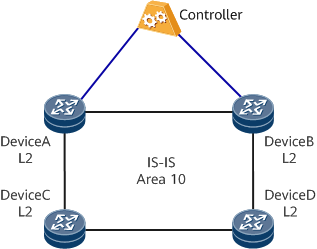
Collecting topology information in an IGP area
In Figure 1, DeviceA, DeviceB, DeviceC, and DeviceD use IS-IS to communicate with each other at the IP network layer. DeviceA, DeviceB, DeviceC, and DeviceD are all Level-2 devices in the same area (area 10). After BGP-LS is deployed on any one of the devices (DeviceA, DeviceB, DeviceC, and DeviceD) and this device establishes a BGP-LS peer relationship with the controller, topology information of the entire network can be collected and reported to the controller. Reliability can be improved by deploying BGP-LS on two or more devices and establishing a BGP-LS peer relationship between each BGP-LS device and the controller. Because the BGP-LS devices collect the same topology information, they back up each other. This means that the topology information can be reported promptly if any of the BGP-LS devices fails.
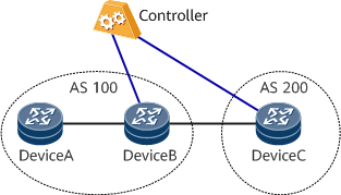
Collecting BGP inter-AS topology information
In Figure 2, DeviceA and DeviceB belong to the same AS, and an IS-IS neighbor relationship is established between them. BGP is not enabled on DeviceA in the AS. An EBGP peer relationship is established between DeviceB and DeviceC. If BGP-LS is not enabled, topology information cannot be transmitted between the ASs. Because the devices collect information about only their own AS, the topology information in AS 100 is different from that in AS 200. In this case, BGP-LS must be enabled on at least one device in each AS and this device must establish a BGP-LS peer relationship with the controller. To ensure that topology information can be collected and reported reliably, enable that two or more devices in each AS are connected to the controller.
On the network shown in Figure 3, two controllers are each connected to a device in a different AS. If both controllers need to obtain information about the entire network's topology, a BGP-LS peer relationship needs to be established between the controllers or between the devices (DeviceB and DeviceC in this example) connected to the controllers.
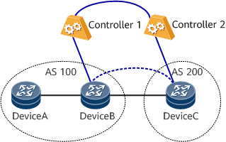

To minimize the number of connections with the controllers, one or more devices can be used as BGP-LS RRs, which then function as proxies to establish BGP-LS peer relationships between the devices and controllers.
Usage Scenario
The router functions as a forwarder and reports topology information to the controller for topology monitoring and traffic control.
Benefits
BGP-LS offers the following benefits:
- Reduces computing capability requirements on the controller.
- Allows the controller to gain the complete inter-AS topology information.
- Requires only one routing protocol (BGP) to report topology information to the controller.