VPWS in BGP Mode
Definition
BGP VPWS uses BGP as the signaling protocol to transmit Layer 2 information and VC labels between PEs.
BGP VPWS uses VPN targets to identify different VPNs, creating greater flexibility for VPN networking. BGP VPWS assigns VC labels from label blocks. A label block is allocated to each CE in advance. The size of the label block allocated to a CE determines the number of connections that the CE can establish with other CEs. BGP VPWS allows allocation of additional labels to a CE for future VPN capacity expansion. PEs figure out the inner labels of packets based on these label blocks and then transmit packets based on inner labels. BGP VPWS has good scalability and supports both local and remote connections.
Basic Concepts
BGP VPWS can use label blocks to allocate labels to multiple connections at the same time. The CE range specified for a CE indicates the number of connections that can be established between this CE and other CEs. Only one label block can be allocated to a CE at one time. The label block size equals the CE range. The practice of additional label allocation may waste labels in the short term, but will reduce configuration workload during future VPN capacity expansion. Assume that an enterprise VPN has 10 CEs and the number may increase to 20 due to service expansion in the future. In this situation, you can set the CE range for each CE to 20 to reserve labels for the 10 CEs to be added later.
Implementation
Packet forwarding by BGP VPWS is similar to that by LDP VPWS. The two types of VPWS both use standard Layer 2 labels, but use different signaling protocols to exchange these labels: LDP VPWS uses extended LDP, whereas BGP VPWS uses MP-BGP.

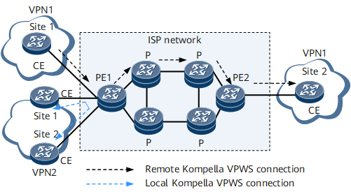
- Configure VPN1 on each PE and bind local CEs to VPN1. For example, bind CE1, CE2, and CE3 to VPN1 on PE1.
- Allocate label blocks to CEs. Here, each CE connects to five CEs. Therefore, a label block containing at least five labels must be allocated to each CE.
- On each PE, specify peer CE IDs and PE interfaces connecting to local CEs.
Like CCC VPWS, BGP VPWS also supports local connections. It is easy to use BGP VPWS to establish full-mesh connections.
VC Label Calculation
A label block is a consecutive range of labels. BGP VPWS uses MP-BGP as the signaling protocol to transmit label block information.
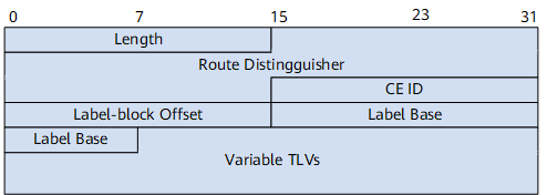
For a clear description of the label block, several parameters are defined: Label Base (LB), initial label of the label block, Label Range (LR), and Label-Block Offset (LO), as shown in Figure 3.
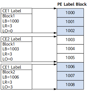
When adding CE information to a PE, you must specify the LR. The LB is automatically allocated by the PE. This label block is used as a network layer reachable information (NLRI) entry and transmitted to other PEs through BGP. When CE information is deleted or the connection between the PE and CE becomes invalid, the label block is deleted. Meanwhile, BGP sends a Withdraw message for notification. Assume that when BGP VPWS is deployed, CE1 needs to establish two VCs with other remote CEs; then the size of the label block cannot be smaller than 2. Considering future capacity expansion, you can define the range as 10.
The labels may be insufficient as VCs increase, regardless of the range. If this situation occurs, redefine the range for a larger label space. A problem then arises. As mentioned earlier, the data of the label block is transmitted through the BGP NLRI, and this label block is used to calculate VC labels and forward data. To protect the original VC connection, you can allocate a new label block to this CE and advertise the label block as a new NLRI through BGP. In other words, the label space of a CE may consist of multiple label blocks. The LO defines the relationship between multiple labels. The LO of a label block identifies the total size of the label blocks preceding this label block. For example, if the LR of the first label block is 100 and the LO is 0, and the LR of the second label block is 50, then the LO of the second label block is 100. Then the LO of the third label block if any is 150. The LO is used in calculating VC labels. Therefore, a label block can be defined by three parameters: LB, LR, and LO.
- A CE ID uniquely identifies a CE in a VPN. In a VPN, CE IDs must be unique. The CE ID is carried in each NLRI; different label blocks can therefore be associated with their corresponding CEs.
- CE IDs can also be used to calculate VC labels. For this reason, they cannot be chosen at random. The condition x > y must be met if the range of the local CE is x and the local CE connects to a peer CE with the CE ID being y. Otherwise, the value of x must be increased to meet the preceding condition.
Item |
Description |
Item |
Definition |
|---|---|---|---|
Label block allocated by PE-1 to CE-m |
Lm |
Label block allocated by PE-2 to CE-n |
Ln |
LO of Lm |
LOm |
LO of Ln |
LOn |
LB of Lm |
LBm |
LB of Ln |
LBn |
LR of Lm |
LRm |
LR of Ln |
LRn |
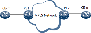
Assume that PE1 and PE2 establish a VC between CE-m and CE-n that belong to the same VPN.
PE1 receives a label block LBn/LRn/LOn from PE2.
PE1 checks whether the encapsulation type of CE-n received from PE2 is the same as that of CE-m. If not, PE1 stops processing.
PE1 checks the CE ID to see whether m = n. If m = n, PE1 reports an error and stops processing.
If CE-m has multiple label blocks, PE1 checks whether these label blocks meet the condition LOm <= n < LOm + LRm. If the condition is not met, PE1 reports an error and stops processing.
PE1 checks whether all the label blocks related to CE-n meet the condition LOn <= m < LOn + LRn. If the condition is not met, PE1 reports an error and stops processing.
PE1 checks whether the outer tunnel between PE-m and PE-n is established normally. If not, PE1 stops processing. The outer tunnel is assumed as an LSP tunnel with the label as Z.
PE1 allocates an inner label (LBn + m - LOn), the outgoing label of the VC, to CE-n; PE1 allocates an inner label (LBm + n - LOm), the incoming label of the VC, to CE-m.
The label of the outer tunnel from PE2 to PE1 is Z.
After the inner and outer labels are calculated and the VC is Up, Layer 2 packets can be transmitted.
The following example describes the process of allocating CE label blocks phase by phase.
Assume that all PEs exchange label block information through BGP. All the public network LSP tunnels are Up. Only VC labels need to be calculated. The ID of CE1 is 1; the ID of CE2 is 2; and the rest can be deduced by analogy.
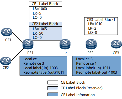
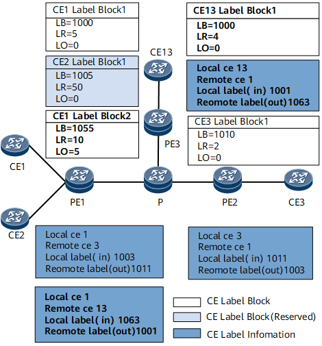
On the network shown in Figure 5, label blocks are allocated to CE1 and CE3 as follows:
PE1 allocates a label block LB/LR/LO = 1000/5/0 to CE1 and receives the label block LB/LR/LO = 1010/2/0 allocated to CE3 from PE2. According to the preceding calculation rule, the incoming and outgoing labels of the VC can be calculated.
PE1 also connects to CE2. Following the allocation of the label block to CE1, PE1 allocates a label block LB/LR/LO = 1005/50/0 to CE2. At the moment, CE2 does not establish any connection with other CEs. The label block is allocated for future capacity expansion. Therefore, PE1 does not calculate labels for CE2.
PE1 determines whether the label block allocated to CE1 meets the requirement LOm <= n < LOm + LRm. Because, LOm is 0, n is 3, and LRm is 5, this requirement is met. PE1 also re-determines whether this label block meets the requirement LOn <= m < LOn + LRn. Because LOn is 0, m is 1, and LRn is 2, this requirement is also met.
PE1 calculates the incoming and outgoing VC labels. The outgoing VC label (inner label of CE3) is LBn + m - LOn = 1010 + 1 - 0 = 1011. The incoming VC label (inner label of CE1) is LBm + n - LOm = 1000 + 3 - 0 = 1003.
PE2 determines whether the label block allocated by PE1 to CE1 meets the requirement LOm <= n < LOm + LRm. Because LOm is 0, n is 1, and LRm is 2, this requirement is met. PE1 also re-determines whether this label block meets the requirement LOn <= m < LOn + LRn. Because LOn is 0, m is 3, and LRn is 5, this requirement is also met.
PE2 calculates the incoming and outgoing VC labels. The outgoing VC label (inner label of CE1) is LBn + m - LOn = 1000 + 3 - 0 = 1003. The incoming VC label (inner label of CE3) is LBm + n - LOm = 1010 + 1 - 0 = 1011.
As shown in Figure 6, if CE13 is added to the VPN, a VC must be established between CE13 and CE1. PE3 allocates a label block LB/LR/LO = 1000/4/0 to CE13. A new VC needs to be established between CE1 and CE13.
Whether the ID of CE13 is appropriate is judged in a similar way. PE1 determines whether the label block allocated to CE1 meets the requirement LOm <= n < LOm + LRm. Because LOm is 0, n is 13, and LRm is 5, this requirement is not met. PE1 determines whether the label block allocated to CE1 meets the requirement LOn <= m < LOn + LRn. Because, LOn is 0, m is 1, and LRn is 4, this requirement is met.
The CE ID 13 is greater than the LO + LR of CE1; therefore, the outgoing VC label (inner label of CE1) cannot be calculated. You need to modify the label range of CE1 on PE1 to 15 in this example, and allocate another label block to CE1 with the label range as 10. Following the allocation of the label block to CE2, PE1 allocates a second label block LB/LR/LO = 1055/10/5 to CE1. PE1 re-determines whether this label block meets the requirement LOm <= n < LOm + LRm. Because, LOm is 5, n is 13, and LRm is 10, this requirement is also met. PE1 also re-determines whether this label block meets the requirement LOn <= m < LOn + LRn. Because LOn is 0, m is 1, and LRn is 4, this requirement is also met.
Similarly, PE3 receives the two label blocks LB/LR/LO = 1000/5/0 and LB/LR/LO = 1055/10/5 allocated by PE1 to CE1. Only the label block LB/LR/LO = 1055/10/5 meets the requirement.
PE1 determines that labels must be allocated from the second label block of CE1. The outgoing VC label calculated by PE1 is LBn + m - LOn = 1000 + 1 - 0 = 1001. The incoming VC label calculated by PE1 is LBm + n - LOm = 1055 + 13 - 5 = 1063.
According to the formula, PE3 calculates the VC labels. The outgoing VC label calculated by PE3 is LBm + n - LOm = 1055 + 13 - 5 = 1063; the incoming label calculated by PE3 is LBn + m - LOn = 1000 + 1 - 0 = 1001.
The preceding example shows that though the label allocation method used by BGP VPWS consumes a large number of labels, the number of VCs established on a PE is limited. Therefore, the label consumption can be ignored.
In practical network deployment, the network administrator is used to identifying the location of a CE by CE ID. If large CE IDs are used, a lot of label spaces will be consumed. In extreme cases, the valid label range will be insufficient. To solve this problem, use CE names to describe CE locations and create a table to record actual CE IDs.
Signaling for Transmitting VC Labels
BGP VPWS extends the NLRI of MP-BGP to transmit VC information. Like L3VPN, BGP VPWS also uses the route distinguisher (RD) and VPN target. Because VPWS is a P2P technology, a CE has to use multiple interfaces or sub-interfaces to establish VCs with multiple other CEs. Even if in the same VPN, two CEs must connect over a VC.
Figure 7 describes label block information in the NLRI. The circuit status vector (CSV) in the TLV with variable length is used to describe the LR and tunnel status of the label block.
An extended community attribute is defined to carry more L2VPN information, as shown in Figure 8.
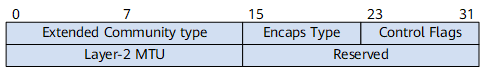
Table 2 describes each field shown in Figure 8.
Field |
Description |
Number of Bits |
Description |
|---|---|---|---|
Extended Community Type |
Extended information type |
16 |
Extended community type |
Encaps Type |
Encapsulation type |
8 |
Layer 2 encapsulation type |
Control Flags |
Control word |
8 |
Control word |
Layer-2 MTU |
Layer 2 MTU |
16 |
- |
Reserved |
Reserved |
16 |
Reserved |
Usage Scenario
BGP VPWS applies to networks with dense Layer 2 connections, such as a network with the mesh topology.
Benefits
BGP VPWS does not directly perform operations on connections between CEs. It partitions the entire ISP network into different VPNs and numbers each CE in each VPN. Similar to BGP/MPLS VPN, BGP VPWS uses the VPN target to control the sending and receiving of VPN routes, creating greater networking flexibility.