VPN MPLS/VPN SRv6 Dual-Stack Tunnel
Typical Application Scenario of VPN MPLS/VPN SRv6 Dual-Stack Tunnels
When an MPLS backbone network that carries VPN routes spans multiple ASs, inter-AS VPN technology is used to deploy L3VPN over MPLS services. As IPv4 addresses gradually run out, IPv6 networks will be increasingly deployed to solve this issue. However, such an evolution cannot take place overnight, causing IPv4 and IPv6 services to coexist.
To prevent existing services from being compromised during the upgrade and evolution of existing networks, VPN MPLS/VPN SRv6 dual-stack tunnels can be used. Such tunnels not only prevent traffic interruption when IPv4 and IPv6 services coexist, but also make it much more feasible to transition from IPv4 to IPv6.
On the network shown in Figure 1, an end-to-end VPNv4 IPv4 BGP peer relationship, a VPNv4 IPv6 BGP peer relationship, and an SRv6 BE tunnel are established between PE1 and PE2.
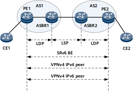
Services are deployed in the following process:
- An end-to-end VPNv4 IPv4 BGP peer relationship is established between PE1 and PE2. The route to CE1 is advertised to PE2 through the VPNv4 IPv4 BGP peer relationship. After receiving the route, PE2 adds the route to its VPN instance, which then sends the route to CE2.
- PE1 and PE2 are configured to preferentially select routes with IPv4 next hops based on their high priority using the peer ipv4–address high-priority command.
- SRv6 BE services are deployed between PE1 and PE2.
- A VPNv4 IPv6 BGP peer relationship is established between PE1 and PE2, and the devices are enabled to exchange IPv4 prefix SID information with each other using the peer ipv6–address prefix-sid command.
- PE1 is enabled to add SIDs to VPN routes using the segment-routing ipv6 locator locator-name command in PE1's VPN instance that connects to CE1.
- After PE1 receives a VPN route from its VPN instance, PE1 advertises a copy of this route to the VPNv4 IPv4 BGP peer and applies for an MPLS label. PE1 then advertises another copy to the VPNv4 IPv6 BGP peer, with the route carrying a SID. A route without a SID cannot be advertised to the VPNv4 IPv6 BGP peer.
- PE2 receives two VPN routes with the same prefix, but one with an IPv4 next hop and the other with an IPv6 next hop. PE2 then adds the two routes to its VPN instance that connects to CE2.
- After CE2 receives the two routes, the route with the IPv4 next hop recurses to the MPLS tunnel, and the route with the IPv6 next hop recurses to the SRv6 tunnel.
- After the route with the IPv6 next hop becomes stable, the peer ipv6–address high-priority and undo peer ipv4–address high-priority commands are run on PE2 to trigger a change in route preference. In this way, the preferred route switches from that with the IPv4 next hop to that with the IPv6 next hop, and user traffic switches from the traditional MPLS tunnel to the SRv6 tunnel accordingly.
Application Scenario of VPN MPLS/VPN SRv6 Dual-Stack Tunnels (with RRs)
On the network shown in Figure 2, an end-to-end VPNv4 IPv4 BGP peer relationship, a VPNv4 IPv6 BGP peer relationship, and an SRv6 BE tunnel are established between PE1 and PE2.
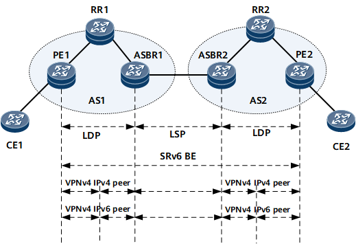
Services are deployed in the following process:
In AS1, VPNv4 IPv4 BGP peer relationships are established between PE1 and RR1 and between RR1 and ASBR1. The next hop of a VPNv4 route is not changed when the route is being reflected by RR1.
In AS2, VPNv4 IPv4 BGP peer relationships are established between PE2 and RR2 and between RR2 and ASBR2. The next hop of a VPNv4 route is not changed when the route is being reflected by RR2.
PE1, ASBR1, ASBR2, and PE2 are configured to preferentially select routes with IPv4 next hops based on their high priority using the peer ipv4–address high-priority command.
SRv6 BE services are deployed between PE1 and PE2.
VPNv4 IPv6 BGP peer relationships are established between PE1 and RR1, between RR1 and ASBR1, between ASBR2 and RR2, and between RR2 and PE2. The devices are enabled to exchange IPv4 prefix SID information with specified IPv6 peers using the peer ipv6–address prefix-sid command.
CE1 advertises VPN route A to PE1, and PE1 sends the route to the VPNv4 address family. After finding that route A is a locally leaked VPN route, the VPNv4 address family advertises route A to RR1 through the VPNv4 IPv4 and IPv6 peer relationships separately.
RR1 receives two routes with the same prefix but different next hops from its IPv4 and IPv6 BGP peers. According to the BGP route advertisement policy, the RR advertises only the optimal route to ASBR1. This may lead to just one link being available to the same destination address during data transmission. To address this issue, you can deploy the BGP Add-Path feature on RR1 so that the router can advertise multiple routes with the same prefix to its BGP peers. Specifically, RR1 reflects the VPNv4 route with the IPv4 next hop to the IPv4 BGP peer, and reflects the VPNv4 route with the IPv6 next hop to the IPv6 BGP peer. In this way, multiple links to the same destination address are formed.
ASBR1 receives two VPN routes with the same prefix, but one with an IPv4 next hop and the other with an IPv6 next hop. ASBR1 adds both routes to its VPN instance. After the VPN instance receives the two remotely leaked routes, the route with the IPv4 next hop recurses to the MPLS tunnel, and the route with the IPv6 next hop recurses to the SRv6 tunnel.
CE2 switches traffic to the SRv6 BE tunnel, through which traffic is forwarded to ASBR1. Then ASBR1 also switches traffic to the SRv6 BE tunnel.
Route Regeneration Scenario with VPN MPLS/VPN SRv6 Dual-Stack Tunnels
On the network shown in Figure 3, a VPNv4 IPv6 BGP peer relationship and an SRv6 tunnel are established between PE1 and PE2. A VPNv4 IPv4 BGP peer relationship and an MPLS tunnel are established between PE2 and PE3.

Services are deployed in the following process:
PE3 advertises a route to PE2 through the VPNv4 IPv4 BGP peer relationship, and then PE2 advertises the route to PE1 through the VPNv4 IPv6 BGP peer relationship. Route advertisement from PE1 to PE3 follows the same process but in reverse.
PE2 advertises the route (received from PE3) with the IPv4 next hop to PE1, and advertises the route (received from PE1) with the IPv6 next hop to PE3.
Route regeneration is enabled on PE2. Specifically, after the VPNv4 routes received from PE3 and PE1 are added to PE2's VPN instance, the VPN instance is configured to advertise regenerated routes to the VPNv4 address family using the advertise route-reoriginate command.
PE2 is enabled to advertise the routes regenerated in the VPNv4 address family to the VPNv4 IPv4 and IPv6 BGP peers using the peer ipv4-address advertise route-reoriginated vpnv4 and peer ipv6-address advertise route-reoriginated vpnv4 commands, respectively.