BIERv6 I-PMSI Tunnel Establishment
PMSI tunnels are logical channels established between PEs to transmit C-multicast data over the public network. An I-PMSI tunnel connects all PEs in the same MVPN and is typically used as the default tunnel for data forwarding.
Figure 1 shows the process of establishing a BIERv6 I-PMSI tunnel. PE1 is the sender PE, and PE2 and PE3 are receiver PEs.
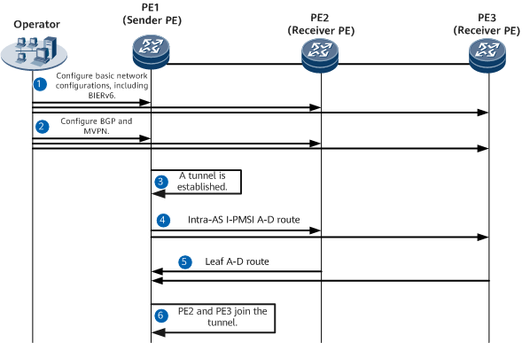
Table 1 describes the process of establishing a BIERv6 I-PMSI tunnel.
Step |
Device |
Description |
|---|---|---|
1 |
PE1, PE2, and PE3 |
Complete basic network configurations, including BIERv6 network configurations. |
2 |
PE1, PE2, and PE3 |
Configure BGP and MVPN. |
3 |
PE1 |
Configure PE1 as a sender PE and set the I-PMSI tunnel type to BIER in the IPv6 MVPN I-PMSI view. |
4 |
PE1 |
PE1 sends an Intra-AS I-PMSI A-D route to PE2 and PE3 through BGP peer relationships. The route carries the following information:
In G-BIER scenarios, in addition to MVPN RT and PMSI tunnel attribute information, the routes advertised by PE1 carry the MSID attribute, which contains the following information:
|
5 |
PE2 and PE3 |
After receiving the route from PE1, PE2 and PE3 reply with a Leaf A-D route. The route carries the following information:
|
6 |
PE1 |
After receiving the routes from PE2 and PE3, PE1 records PE2 and PE3 as MVPN members and sets their bit positions in the BIERv6 BitString corresponding to the tunnel to 1. Consequently, PE2 and PE3 join the BIERv6 I-PMSI tunnel. |