AC Power Distribution Guide

Do not install power cables when the power is on. This is to avoid injuries.

AC Power Supply System
For cable specifications, see Cables in Hardware Description.
Item |
Description |
Remarks |
|---|---|---|
Circuit breaker of each channel |
≥ 16 A NOTICE:
The circuit breaker current must not be greater than the maximum derating current of the device. |
- |
Installing Power Cables
- Route AC power cables along the cable ladder and lay them on the chassis.
- Insert the AC power cable to the AC input port and secure it using the loose-proof pinch as shown in Figure 2. Connect the other end of the AC power cable to the PDF of the equipment room.
- Use cable ties to bundle AC cables every 150 mm upwards from the bottom and fasten the cables to the cable tray.
- Attach permanent labels 20 mm from both ends of each AC power cable.

Instructions for Connecting the AC Power Cable to the Power Distribution Box
Cut the PE ground wire (yellow-green wire) at the peeling place (wrap it with insulation tape to prevent leakage or short circuit), peel the L wire (brown wire) and N wire (blue wire) and crimp the OT terminal Or cold-pressed terminal (terminal type is selected according to actual conditions).

The colors of AC power cables vary with countries and regions. Cables purchased at local markets must comply with local rules and regulations.
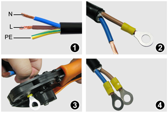
Connect the L and N wires to the corresponding L and N input terminals of the power distribution box.
When using 110V power supply (dual live wire power supply), L and N are connected to the two live wires (L) of the equipment room and connected to the PGND cable. At the same time, both L and N poles must be configured with circuit breakers.