S5720I-6X-PWH-SI-AC
Version Mapping
Table 1 lists the mapping between the S5720I-6X-PWH-SI-AC chassis and software versions.
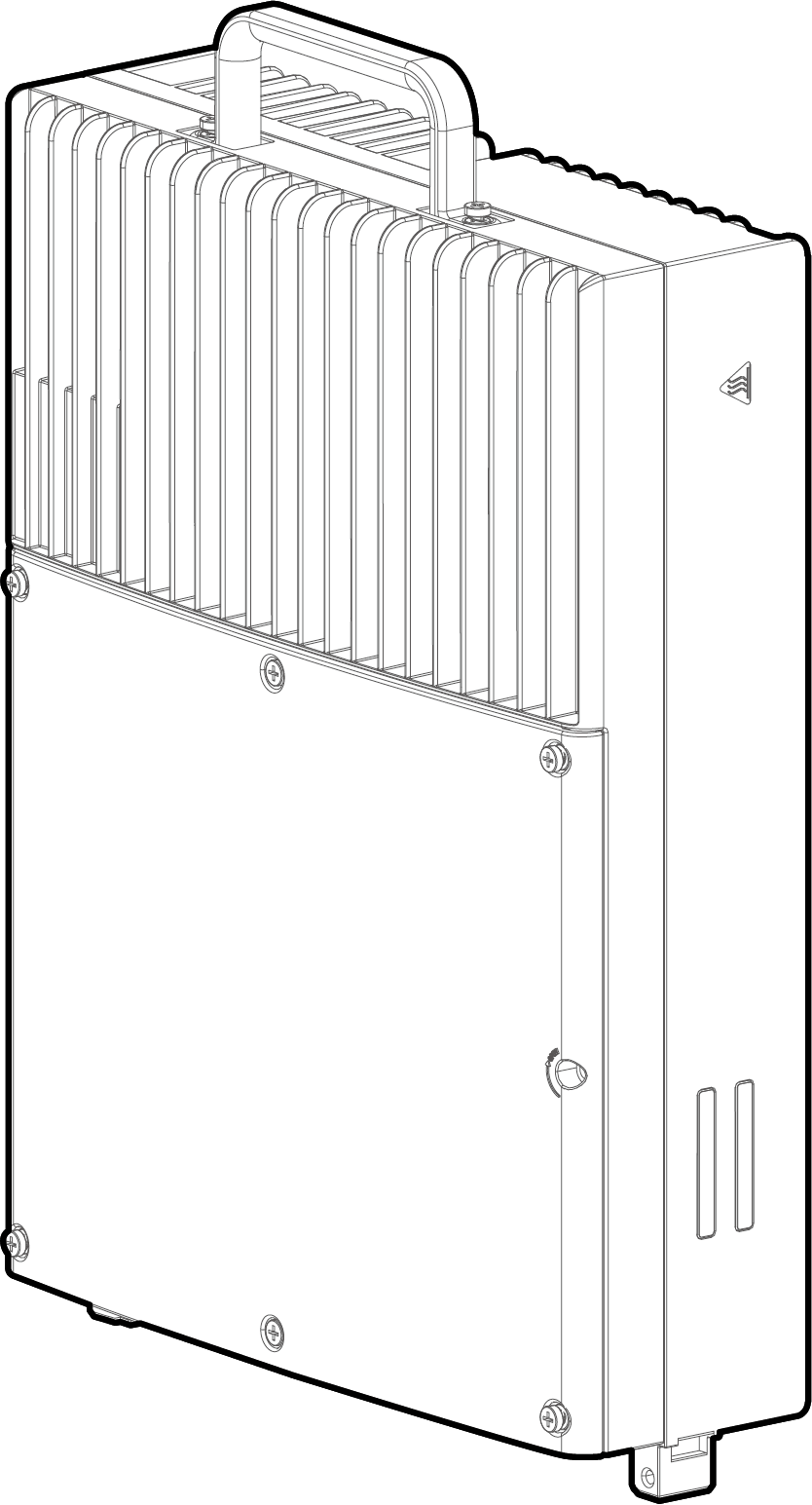
Appearance and Structure
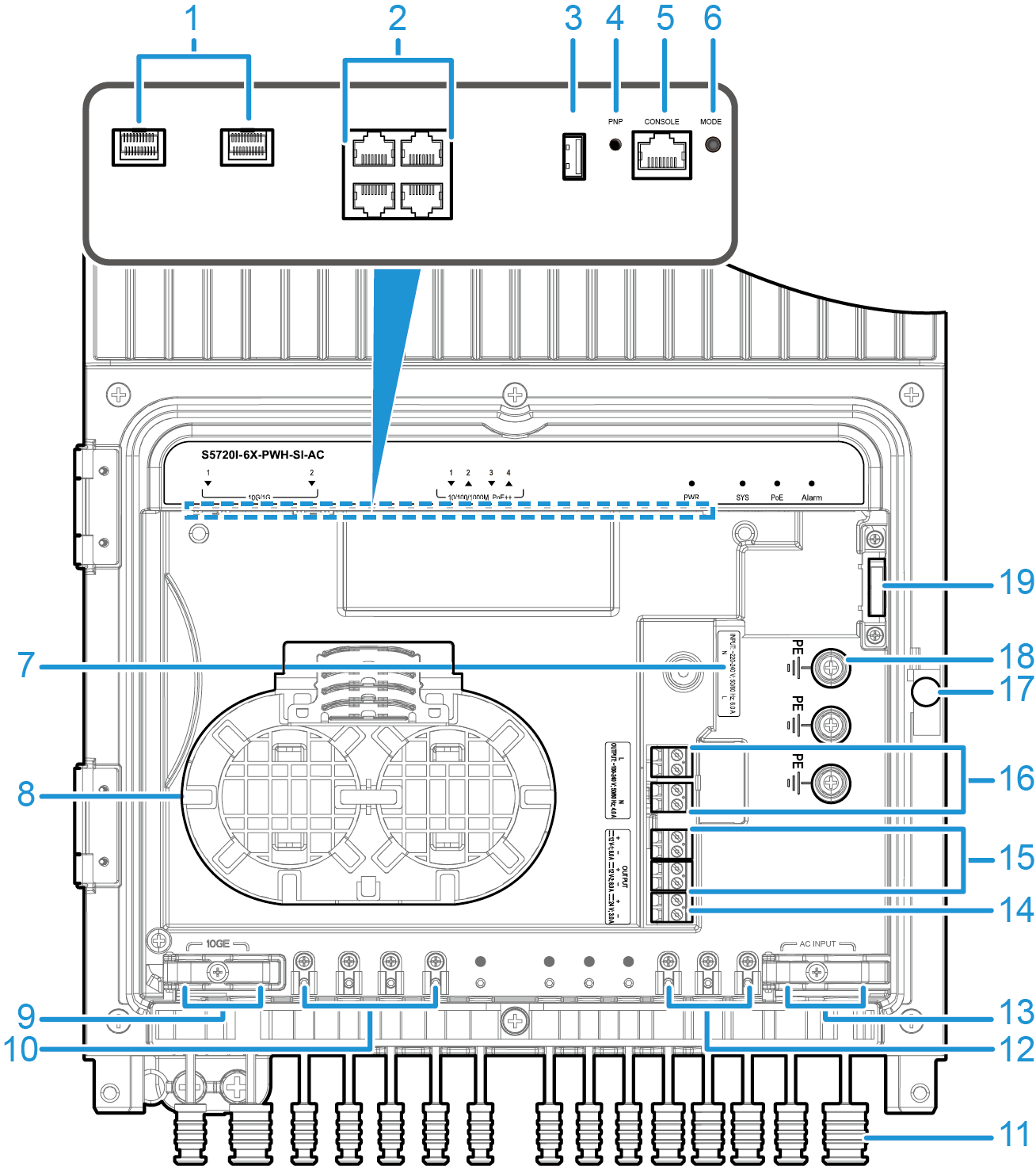
1 |
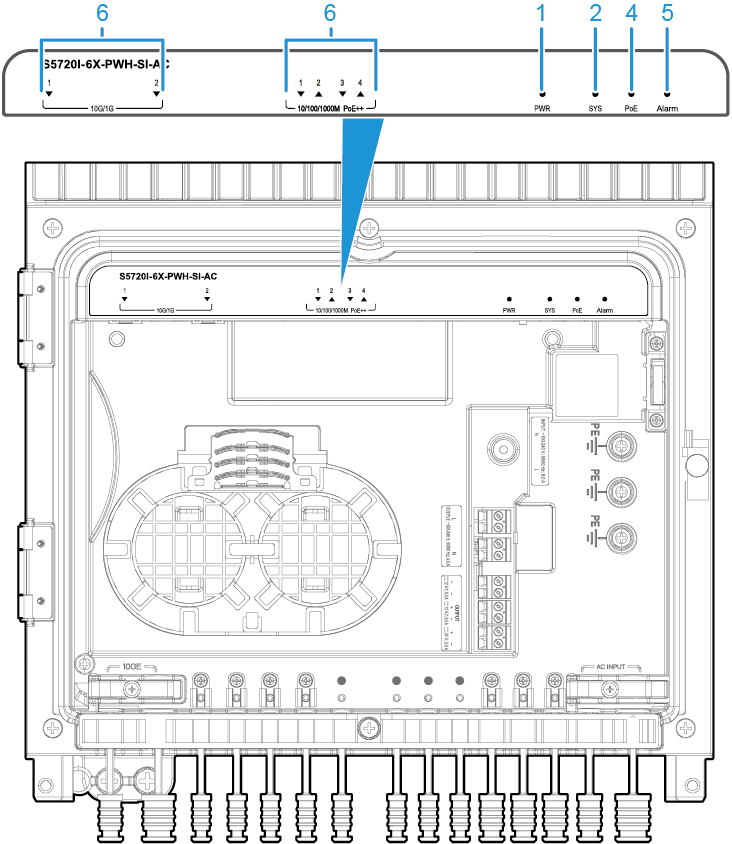
Two 10GE SFP+ ports Applicable modules and cables:
NOTE:
If one port uses a GPON optical module, the other port cannot be used. The locking bar of an optical port is upward. If an optical module cannot be completely inserted into the optical port, do not force it into the port. Turn the optical module 180 degrees and try again. |
2 |
Four PoE++ 10/100/1000BASE-T ports |
3 |
One USB port |
4 |
One PNP button NOTICE:
To restore the factory settings and reset the switch, hold down the button for at least 6 seconds. To reset the switch, press the button. Resetting the switch will cause service interruption. Exercise caution when you press the PNP button. |
5 |
One console port |
6 |
MODE button NOTE:
The switch supports two indicator modes: status (default mode) and PoE. To change the current indicator mode, press the MODE button. Hold down the MODE button for 6 seconds and release it to start the web initial login mode. Either of the following situations will occur:
|
7 |
AC power input socket NOTICE:
The external power supply system must be connected to a circuit breaker (20 A is recommended). For safety purposes, do not use a switch without a circuit breaker. An AC power input socket is used with a power connector, which is included in the installation accessory package delivered with the switch. A power cable needs to be connected to the power connector onsite. If no power cable is available, you can purchase one (part number: 25030398) from Huawei. |
8 |
Fiber management tray (FMT) NOTE:
The FMT is removable. A maximum of four fused fibers are supported. Maximum length of a fiber that can be coiled up in the FMT: 20 m (for a single bare fiber) or 1 m (for a single fiber pigtail). If two fibers are used, this length is halved. |
9 |
Two optical fiber outlets NOTE:
The diameter of optical fibers supported: 8±0.5 mm to 9.6±0.5 mm (on the left outlet) and 13.3±0.5 mm (on the right outlet). |
10 |
Four Ethernet cable outlets NOTE:
Cat5e and Cat6 Ethernet cables are supported. |
11 |
Rubber bungs for cable outlets NOTE:
Rubber bungs must be inserted into the idle cable outlets. |
12 |
Three DC or AC output power cable outlets NOTE:
The diameter of power cables supported by an outlet is 9.3±0.5 mm. |
13 |
Two AC input power cable outlets NOTE:
The diameter of power cables supported: 9.5±0.5 mm (on the left outlet) and 14±0.5 mm (on the right outlet). |
14 |
AC power output socket 2 NOTE:
The switch provides one 24 V AC output to external devices, such as strobe lights and non-PoE PTZ dome cameras. One 24 V AC output provides a maximum of 72 W power. |
15 |
DC power output socket NOTE:
The switch provides two 12 V DC outputs to external devices, such as strobe lights and non-PoE PTZ dome cameras. Two 12 V DC outputs provide a total of 48 W power. The maximum power of a single output is 48 W. Two 12 V DC outputs and one 24 V AC output share power resources with PoE output. The total shared power is 150 W. |
16 |
AC power output socket 1 NOTICE:
Cables need to be connected to an AC power output socket onsite. Pay attention to the position of the L and N labels, ensuring that the cables are connected in the correct sockets. The switch provides 220 V AC power to external devices, such as strobe lights and non-PoE PTZ dome cameras. The maximum output current is 4 A. The internal 220 V AC power supply is used only for external power conversion. It has no circuit breaker, regulated voltage circuit, or surge protection. The connected devices must provide certain surge protection capabilities. Recommended values are 20 kA in differential mode and 20 kA in common mode. |
17 |
Latch of the maintenance compartment NOTE:
|
18 |
PE cable ground terminal NOTE:
It is used to ground a PE power cable for 220 V AC input or output. |
19 |
Door-opening alarm button NOTE:
When the door of the maintenance compartment is opened, a door-opening alarm is reported. |
- |
- |
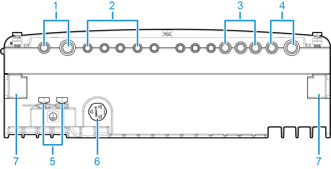
1 |
Two optical fiber outlets NOTE:
The diameter of optical fibers supported: 8±0.5 mm to 9.6±0.5 mm (on the left outlet) and 13.3±0.5 mm (on the right outlet). |
2 |
Four Ethernet cable outlets NOTE:
Cat5e and Cat6 Ethernet cables are supported. |
3 |
Three DC or AC output power cable outlets NOTE:
The diameter of power cables supported by an outlet is 9.3±0.5 mm. |
4 |
Two AC input power cable outlets NOTE:
The diameter of power cables supported: 9.5±0.5 mm (on the left outlet) and 14±0.5 mm (on the right outlet). |
5 |
Ground screw NOTE:
It is used to ground the switch. The ground cable needs to be purchased separately. |
6 |
Atmospheric pressure valve NOTE:
It ensures that the atmospheric pressure inside and outside the switch are the same. |
7 |
Mounting column for a cable cover NOTE:
It is used to mount an optional cable cover. |
- |
- |
Port Description
10/100/1000BASE-T port
Attribute |
Description |
|---|---|
Connector type |
RJ45 |
Standards compliance |
IEEE802.3, IEEE802.3u, IEEE802.3ab |
Working mode |
10/100/1000 Mbit/s auto-sensing |
Maximum transmission distance |
It supports long-distance interconnection with Huawei cameras.
For example, it supports the distance of 200 m at 100 Mbit/s and supports
the distance of 250 m at 10 Mbit/s.
|
10GE SFP+ port
Console port
USB port

USB flash drives from different vendors differ in model compatibility and drivers. If a USB flash drive cannot be used, try to replace it with another one from a mainstream vendor. Switches support a maximum of 128 GB USB flash drives.
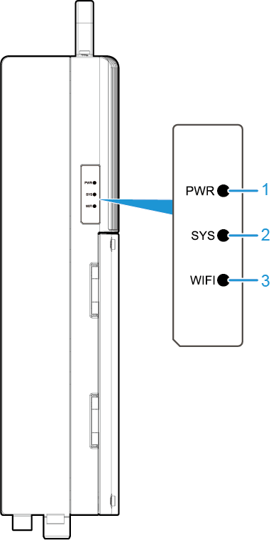
Indicator Description
No. |
Indicator |
Name |
Color |
Status |
Description |
|---|---|---|---|---|---|
1 |
PWR |
Built-in power supply indicator |
- |
Off |
The switch is not powered on. |
Green |
Steady on |
The power module is supplying power normally. |
|||
2 |
SYS |
System status indicator |
- |
Off |
The system is not running. |
Green |
Fast blinking |
The system is starting or is copying the system software and configuration file from a USB flash drive during a USB-based upgrade. |
|||
Green |
Slow blinking |
The system is operating properly. |
|||
Red |
Steady on |
The system does not work normally after registration, or a temperature alarm has been generated. |
|||
Red |
Blinking |
The system cannot be upgraded after a USB flash drive is inserted. The USB-based upgrade failed. |
|||
Yellow |
Blinking |
The switch has restarted after a successful upgrade using a USB flash drive. You can remove the USB flash drive from the switch. |
|||
3 |
WIFI |
Wi-Fi indicator |
Red |
Fast blinking |
The Wi-Fi function is reserved for future use. You can configure the WIFI indicator on a switch to fast blink red, helping field maintenance personnel quickly find the switch. |
4 |
PoE |
PoE indicator |
- |
Off |
The PoE mode is not selected. |
Green |
Steady on |
The PoE mode is selected. In this mode, the service port indicators show the PoE status. After 45 seconds, the service port indicators automatically restore to the status mode. This indicator is steady green after you successfully log in to the switch for the first time using the MODE button. |
|||
Green |
Blinking |
If you fail to log in to the switch for the first time using the MODE button, this indicator fast blinks for 10 seconds, and then returns to the default status. |
|||
5 |
Alarm |
12 V DC and 24 V AC output power indicator |
- |
Off |
The 12 V DC or 24 V AC power supply is not in use or the output is normal. |
Red |
Steady on |
A short circuit has occurred for the 12 V DC or 24 V AC power supply. Check whether the external device is short-circuited. |
|||
6 |
- |
Service port indicator |
Meanings of service port indicators vary in different modes. For details, see Table 6. |
||
Display Mode |
Color |
Status |
Description |
|---|---|---|---|
Status |
- |
Off |
The port is not connected or has been shut down. |
Green |
Steady on |
A link has been established on the port. |
|
Green |
Blinking |
The port is sending or receiving data. |
|
PoE |
- |
Off |
The port is not providing power to a powered device (PD). |
Green |
Steady on |
The port is providing power to a PD. |
|
Yellow |
Steady on |
The PoE function is disabled on the port. |
|
Yellow |
Blinking |
The port stops providing PoE power because of an exception (for example, an incompatible PD is connected to the port). |
|
Green and yellow |
Blinking green and yellow alternately |
The port fails to supply power to a PD due to one of the following reasons:
|
Power Supply Configuration
The S5720I-6X-PWH-SI-AC has a built-in power module and does not support pluggable power modules. The S5720I-6X-PWH-SI-AC can be connected to an external 220 V AC power supply. Table 7 lists power supply configurations.
Power Supply Configuration |
Available PoE Power |
Maximum Number of Ports (Fully Loaded) |
|---|---|---|
External 220 V AC power supply |
150 W |
|
The PoE output shares power resources with two 12 V DC outputs and one 24 V AC output. The shared power is 150 W.
Heat Dissipation
The S5720I-6X-PWH-SI-AC has no fans and uses natural heat dissipation.
Technical Specifications
Table 8 lists technical specifications of the S5720I-6X-PWH-SI-AC.
Item |
Description |
|---|---|
Memory (RAM) |
512 MB |
Flash |
512 MB in total. To view the available flash memory size, run the display version command. |
Mean time between failures (MTBF) |
41.29 years |
Mean time to repair (MTTR) |
2 hours |
Availability |
> 0.99999 |
Service port surge protection |
±1.5 kV in differential mode, ±6 kV in common mode |
Power supply surge protection |
Impulse current:
Surge:
|
Dimensions (H x W x D) |
390 mm x 300 mm x 110 mm (15.4 in. x 11.8 in. x 4.3 in.) |
Weight (with packaging) |
13.1 kg (28.88 lb) |
Stack ports |
Not supported |
RTC |
Not supported |
RPS |
Not supported |
PoE |
Supported |
Rated voltage range |
220 V AC to 240 V AC, 50/60 Hz |
Maximum voltage range |
176 V AC to 264 V AC, 45 Hz to 66 Hz |
Maximum power consumption (100% throughput) |
|
Typical power consumption (30% of traffic load)
|
25 W |
Operating temperature |
-40°C to +55°C (-40°F to +131°F)
NOTE:
When the altitude is 1800-4000 m (5906-13123 ft.), the highest operating temperature reduces by 1°C (1.8°F) every time the altitude increases by 220 m (722 ft.). The switch can start when the temperature is higher than -25°C (-13°F). |
Storage temperature |
-40°C to +85°C (-40°F to +185°F) |
IP rating |
IP66 |
Noise under normal temperature (27°C, sound power) |
Noise-free (no fans) |
Relative humidity |
5% to 95%, noncondensing |
Operating altitude |
0-4000 m (0-13123 ft.) |
Certification |
|
Part number |
98010835 |