Example for Configuring an IP Unnumbered Interface
Networking Requirements
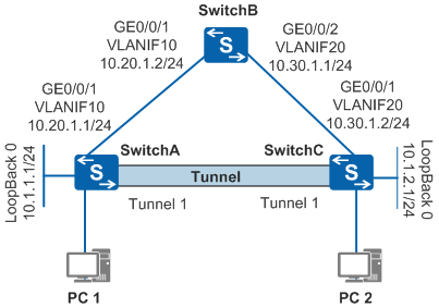
As shown in Figure 1, tunnel interfaces (1) of SwitchA and SwitchC are seldom used, so they have no IP address configured. IP unnumbered needs to be configured on the tunnel interfaces so that the two switches can communicate through the tunnel.
Configuration Roadmap
The configuration roadmap is as follows:
- Create tunnel interfaces on SwitchA and SwitchC, set up a GRE tunnel between them, and specify the source and destination addresses of the tunnel interfaces.
- On SwitchA and SwitchC, configure an IP address for a loopback interface and configure the tunnel interface to borrow the IP address from this loopback interface.
Procedure
- Configure public IP addresses for interfaces connecting the switches and for Loopback0 interfaces.
# Configure SwitchA.
<HUAWEI> system-view
[HUAWEI] sysname SwitchA
[SwitchA] vlan 10
[SwitchA-vlan10] quit
[SwitchA] interface gigabitethernet 0/0/1
[SwitchA-GigabitEthernet0/0/1] port link-type trunk
[SwitchA-GigabitEthernet0/0/1] port trunk allow-pass vlan 10
[SwitchA-GigabitEthernet0/0/1] quit
[SwitchA] interface vlanif 10
[SwitchA-Vlanif10] ip address 10.20.1.1 24
[SwitchA-Vlanif10] quit
[SwitchA] interface loopback 0
[SwitchA-LoopBack0] ip address 10.1.1.1 24
[SwitchA-LoopBack0] quit
# Configure SwitchB.
<HUAWEI> system-view
[HUAWEI] sysname SwitchB
[SwitchB] vlan batch 10 20
[SwitchB] interface gigabitethernet 0/0/1
[SwitchB-GigabitEthernet0/0/1] port link-type trunk
[SwitchB-GigabitEthernet0/0/1] port trunk allow-pass vlan 10
[SwitchB-GigabitEthernet0/0/1] quit
[SwitchB] interface gigabitethernet 0/0/2
[SwitchB-GigabitEthernet0/0/2] port link-type trunk
[SwitchB-GigabitEthernet0/0/2] port trunk allow-pass vlan 20
[SwitchB-GigabitEthernet0/0/2] quit
[SwitchB] interface vlanif 10
[SwitchB-Vlanif10] ip address 10.20.1.2 24
[SwitchB-Vlanif10] quit
[SwitchB] interface vlanif 20
[SwitchB-Vlanif20] ip address 10.30.1.1 24
[SwitchB-Vlanif20] quit
# Configure SwitchC.
<HUAWEI> system-view
[HUAWEI] sysname SwitchC
[SwitchC] vlan 20
[SwitchC-vlan20] quit
[SwitchC] interface gigabitethernet 0/0/1
[SwitchC-GigabitEthernet0/0/1] port link-type trunk
[SwitchC-GigabitEthernet0/0/1] port trunk allow-pass vlan 20
[SwitchC-GigabitEthernet0/0/1] quit
[SwitchC] interface vlanif 20
[SwitchC-Vlanif20] ip address 10.30.1.2 24
[SwitchC-Vlanif20] quit
[SwitchC] interface loopback 0
[SwitchC-LoopBack0] ip address 10.1.2.1 24
[SwitchC-LoopBack0] quit
- Configure OSPF on the switches.
# Configure SwitchA.
[SwitchA] ospf 1
[SwitchA-ospf-1] area 0
[SwitchA-ospf-1-area-0.0.0.0] network 10.20.1.0 0.0.0.255
[SwitchA-ospf-1-area-0.0.0.0] quit
[SwitchA-ospf-1] quit
# Configure SwitchB.
[SwitchB] ospf 1
[SwitchB-ospf-1] area 0
[SwitchB-ospf-1-area-0.0.0.0] network 10.20.1.0 0.0.0.255
[SwitchB-ospf-1-area-0.0.0.0] network 10.30.1.0 0.0.0.255
[SwitchB-ospf-1-area-0.0.0.0] quit
[SwitchB-ospf-1] quit
# Configure SwitchC.
[SwitchC] ospf 1
[SwitchC-ospf-1] area 0
[SwitchC-ospf-1-area-0.0.0.0] network 10.30.1.0 0.0.0.255
[SwitchC-ospf-1-area-0.0.0.0] quit
[SwitchC-ospf-1] quit
- Configure tunnel interfaces 1 to borrow the IP address from Loopback0 and configure the GRE tunnel.
# Configure SwitchA.
[SwitchA] interface tunnel 1
[SwitchA-Tunnel1] tunnel-protocol gre
[SwitchA-Tunnel1] ip address unnumbered interface loopback 0
[SwitchA-Tunnel1] source 10.20.1.1
[SwitchA-Tunnel1] destination 10.30.1.2
[SwitchA-Tunnel1] quit
# Configure SwitchC.
[SwitchC] interface tunnel 1
[SwitchC-Tunnel1] tunnel-protocol gre
[SwitchC-Tunnel1] ip address unnumbered interface loopback 0
[SwitchC-Tunnel1] source 10.30.1.2
[SwitchC-Tunnel1] destination 10.20.1.1
[SwitchC-Tunnel1] quit
- Configure static routes.
# Configure SwitchA.
[SwitchA] ip route-static 10.1.2.0 255.255.255.0 tunnel 1# Configure SwitchC.
[SwitchC] ip route-static 10.1.1.0 255.255.255.0 tunnel 1 - Verify the configuration.
# Ping 10.1.2.1 from SwitchA. The ping operation succeeds.
[SwitchA] ping 10.1.2.1
  PING 10.1.2.1: 56  data bytes, press CTRL_C to break
    Reply from 10.1.2.1: bytes=56 Sequence=1 ttl=255 time=2 ms
    Reply from 10.1.2.1: bytes=56 Sequence=2 ttl=255 time=3 ms
    Reply from 10.1.2.1: bytes=56 Sequence=3 ttl=255 time=3 ms
    Reply from 10.1.2.1: bytes=56 Sequence=4 ttl=255 time=3 ms
    Reply from 10.1.2.1: bytes=56 Sequence=5 ttl=255 time=3 ms

  --- 10.1.2.1 ping statistics ---
    5 packet(s) transmitted
    5 packet(s) received
    0.00% packet loss
    round-trip min/avg/max = 2/2/3 ms
Configuration Files
SwitchA configuration file
#
sysname SwitchA
#
vlan batch 10
#
interface Vlanif10
 ip address 10.20.1.1 255.255.255.0
#
interface GigabitEthernet0/0/1
 port link-type trunk
 port trunk allow-pass vlan 10
#
interface LoopBack0
 ip address 10.1.1.1 255.255.255.0
#
interface Tunnel1
 ip address unnumbered interface LoopBack0
 tunnel-protocol gre
 source 10.20.1.1
 destination 10.30.1.2
#
ospf 1
 area 0.0.0.0
  network 10.20.1.0 0.0.0.255
#
ip route-static 10.1.2.0 255.255.255.0 Tunnel1
#
return
SwitchB configuration file
#
sysname SwitchB
#
vlan batch 10 20
#
interface Vlanif10
 ip address 10.20.1.2 255.255.255.0
#
interface Vlanif20
 ip address 10.30.1.1 255.255.255.0
#
interface GigabitEthernet0/0/1
 port link-type trunk
 port trunk allow-pass vlan 10
#
interface GigabitEthernet0/0/2
 port link-type trunk
 port trunk allow-pass vlan 20
#
ospf 1
 area 0.0.0.0
  network 10.20.1.0 0.0.0.255
  network 10.30.1.0 0.0.0.255
#
return
SwitchC configuration file
#
sysname SwitchC
#
vlan batch 20
#
interface Vlanif20
 ip address 10.30.1.2 255.255.255.0
#
interface GigabitEthernet0/0/1
 port link-type trunk
 port trunk allow-pass vlan 20
#
interface LoopBack0
 ip address 10.1.2.1 255.255.255.0
#
interface Tunnel1
 ip address unnumbered interface LoopBack0
 tunnel-protocol gre
 source 10.30.1.2
 destination 10.20.1.1
#
ospf 1
 area 0.0.0.0
  network 10.30.1.0 0.0.0.255
#
ip route-static 10.1.1.0 255.255.255.0 Tunnel1
#
return