Example for Configuring Routed Proxy ARP
Networking Requirements
In Figure 1, branch A and branch B of an enterprise are located in different cities and their host IP addresses belong to the same network segment 172.16.0.0/16.
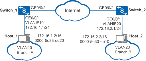
There are reachable routes between Switch_1 connected to branch A and Switch_2 connected to branch B. Branch A and branch B belong to different broadcast domains; therefore, they cannot communicate on a LAN. Hosts in the branches are not configured with default gateway addresses, so they cannot communicate across network segments.
The enterprise requires that branch A and branch B communicate without changing the host configurations.
Configuration Roadmap
The configuration roadmap is as follows:
Add the interface connecting Switch_1 and branch A to VLAN 10 and add the interface connecting Switch_2 and branch B to VLAN 20.
Enable routed proxy ARP on the VLANIF interfaces of branch A and branch B.
Procedure
- Create VLANs, add interfaces to respective VLANs, and configure IP addresses for the interfaces.
# Configure Switch_1.
<HUAWEI> system-view
[HUAWEI] sysname Switch_1
[Switch_1] vlan batch 10
[Switch_1] interface gigabitethernet 0/0/1
[Switch_1-GigabitEthernet0/0/1] port link-type access
[Switch_1-GigabitEthernet0/0/1] port default vlan 10
[Switch_1-GigabitEthernet0/0/1] quit
[Switch_1] interface vlanif 10
[Switch_1-Vlanif10] ip address 172.16.1.1 24
# Configure Switch_2.
<HUAWEI> system-view
[HUAWEI] sysname Switch_2
[Switch_2] vlan batch 20
[Switch_2] interface gigabitethernet 0/0/1
[Switch_2-GigabitEthernet0/0/1] port link-type access
[Switch_2-GigabitEthernet0/0/1] port default vlan 20
[Switch_2-GigabitEthernet0/0/1] quit
[Switch_2] interface vlanif 20
[Switch_2-Vlanif20] ip address 172.16.2.1 24
- Configure routed proxy ARP.
# Configure Switch_1.
[Switch_1-Vlanif10] arp-proxy enable
[Switch_1-Vlanif10] quit
# Configure Switch_2.
[Switch_2-Vlanif20] arp-proxy enable
[Switch_2-Vlanif20] quit
- Verify the configuration.
# Check ARP entries of VLANIF 10 on Switch_1. The command output shows the MAC address corresponding to the IP address of VLANIF 10.
[Switch_1] display arp interface vlanif 10
IP ADDRESS      MAC ADDRESS     EXPIRE(M) TYPE        INTERFACE   VPN-INSTANCE
                                          VLAN/CEVLAN
------------------------------------------------------------------------------
172.16.1.1      101b-5441-5bf6            I -         Vlanif10
------------------------------------------------------------------------------
Total:1         Dynamic:0       Static:0     Interface:1
# Select Host_1 (using Windows 7 as an example) at 172.16.1.2/16 in branch A and select Host_2 at 172.16.2.2/16 in branch B. Ping the IP address of Host_2 on Host_1. The ping operation is successful.
C:\Documents and Settings\Administrator> ping 172.16.2.2
Pinging 172.16.2.2 with 32 bytes of data:
Reply from 172.16.2.2: bytes=32 time<1ms TTL=128
Reply from 172.16.2.2: bytes=32 time<1ms TTL=128
Reply from 172.16.2.2: bytes=32 time<1ms TTL=128
Reply from 172.16.2.2: bytes=32 time<1ms TTL=128

Ping statistics for 172.16.2.2:
    Packets: Sent = 4, Received = 4, Lost = 0 (0% loss),
Approximate round trip times in milli-seconds:
    Minimum = 0ms, Maximum = 0ms, Average = 0ms
# Check the ARP table on Host_1. The command output shows that the MAC address mapping the IP address of Host_2 is the MAC address of VLANIF 10 on Switch_1, indicating that Host_1 and Host_2 can communicate with each other through proxy ARP.
C:\Documents and Settings\Administrator> arp -a
Interface: 172.16.1.2 --- 0xd
  Internet Address      Physical Address      Type
  172.16.2.2            101b-5441-5bf6        dynamic
...
Configuration Files
Switch_1 configuration file
#

sysname Switch_1
#
vlan batch 10
#
interface Vlanif10
 ip address 172.16.1.1 255.255.255.0
 arp-proxy enable
#
interface GigabitEthernet0/0/1
 port link-type access
 port default vlan 10
#
return
Switch_2 configuration file
#

sysname Switch_2
#
vlan batch 20
#
interface Vlanif20
 ip address 172.16.2.1 255.255.255.0
 arp-proxy enable
#
interface GigabitEthernet0/0/1
 port link-type access
 port default vlan 20
#
return