Example for Configuring Intra-VLAN Proxy ARP
Networking Requirements
In Figure 1, hosts of a finance department are in the same VLAN.
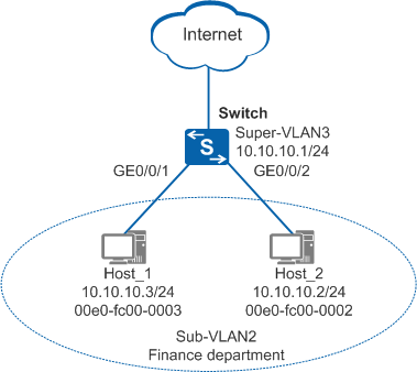
The hosts are often attacked when they access the Internet. They send a large number of broadcast packets, causing broadcast storms in the VLAN and often affecting normal communication.
The company requires that broadcast storms be prevented to ensure communication between hosts and improve information security.
Configuration Roadmap
The configuration roadmap is as follows:
Configure port isolation on the downlink interfaces of the Switch to forbid Layer 2 communication between hosts in the finance department and remove broadcast storms in the VLAN.
Enable intra-VLAN proxy ARP on the VLANIF interface to prevent broadcast storms and implement Layer 3 communication between hosts in the finance department.
Procedure
- Add interfaces to sub-VLAN2 and configure port isolation.
<HUAWEI> system-view
[HUAWEI] sysname Switch
[Switch] vlan batch 2
[Switch] interface gigabitethernet 0/0/1
[Switch-GigabitEthernet0/0/1] port-isolate enable
[Switch-GigabitEthernet0/0/1] port link-type access
[Switch-GigabitEthernet0/0/1] port default vlan 2
[Switch-GigabitEthernet0/0/1] quit
[Switch] interface gigabitethernet 0/0/2
[Switch-GigabitEthernet0/0/2] port-isolate enable
[Switch-GigabitEthernet0/0/2] port link-type access
[Switch-GigabitEthernet0/0/2] port default vlan 2
[Switch-GigabitEthernet0/0/2] quit
- Configure super VLAN3 and add sub-VLAN2 to super VLAN3. Configure an IP address for VLANIF 3 and enable intra-VLAN proxy ARP.
# Configure super VLAN3 and add sub-VLAN2 to super VLAN3.
[Switch] vlan 3
[Switch-vlan3] aggregate-vlan
[Switch-vlan3] access-vlan 2
[Switch-vlan3] quit
# Configure an IP address for VLANIF 3 and enable intra-VLAN proxy ARP.
[Switch] interface vlanif 3
[Switch-Vlanif3] ip address 10.10.10.1 24
[Switch-Vlanif3] arp-proxy inner-sub-vlan-proxy enable
[Switch-Vlanif3] quit
- Configure IP addresses for hosts.
# Assign 10.10.10.3/24 to Host_1.
# Assign 10.10.10.2/24 to Host_2.
- Verify the configuration.
# Check ARP entries of VLANIF 3 on the Switch. The command output shows the MAC address mapping the IP address of VLANIF 3.
[Switch] display arp interface vlanif 3
IP ADDRESS      MAC ADDRESS     EXPIRE(M) TYPE        INTERFACE   VPN-INSTANCE
                                          VLAN/CEVLAN
------------------------------------------------------------------------------
10.10.10.1      101b-5441-5bf6            I -         Vlanif3
------------------------------------------------------------------------------
Total:1         Dynamic:0       Static:0     Interface:1
# Ping the IP address of Host_2 on Host_1 (using Windows 7 as an example). The ping operation is successful.
C:\Documents and Settings\Administrator> ping 10.10.10.2
Pinging 10.10.10.2 with 32 bytes of data:
Reply from 10.10.10.2: bytes=32 time<1ms TTL=128
Reply from 10.10.10.2: bytes=32 time<1ms TTL=128
Reply from 10.10.10.2: bytes=32 time<1ms TTL=128
Reply from 10.10.10.2: bytes=32 time<1ms TTL=128

Ping statistics for 10.10.10.2:
    Packets: Sent = 4, Received = 4, Lost = 0 (0% loss),
Approximate round trip times in milli-seconds:
    Minimum = 0ms, Maximum = 0ms, Average = 0ms
# Check the ARP table on Host_1. The command output shows that the MAC address mapping the IP address of Host_2 is the MAC address of VLANIF 3 on the Switch, indicating that Host_1 and Host_2 can communicate with each other through proxy ARP.
C:\Documents and Settings\Administrator> arp -a
Interface: 10.10.10.3 --- 0xd
  Internet Address      Physical Address      Type
  10.10.10.2            101b-5441-5bf6        dynamic
...
Configuration Files
Switch configuration file
#

sysname Switch
#
vlan batch 2 to 3
#
vlan 3
 aggregate-vlan
 access-vlan 2
#
interface Vlanif3
 ip address 10.10.10.1 255.255.255.0
 arp-proxy inner-sub-vlan-proxy enable
#
interface GigabitEthernet0/0/1
 port link-type access
 port default vlan 2
 port-isolate enable group 1
#
interface GigabitEthernet0/0/2
 port link-type access
 port default vlan 2
 port-isolate enable group 1
#
return