Example for Configuring Inter-VLAN Proxy ARP
Networking Requirements
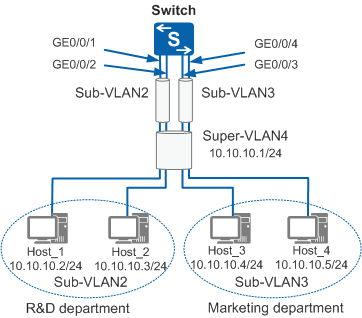
In Figure 1, the IP addresses of the hosts in the R&D and marketing departments belong to the same network segment but different VLANs. The enterprise requires that hosts in the two departments communicate with each other.
Configuration Roadmap
The configuration roadmap is as follows:
Configure a super VLAN and sub-VLANs, and add interfaces to sub-VLANs.
Configure IP addresses for VLANIF interfaces in the super VLAN and enable inter-VLAN proxy ARP.
Procedure
- Configure a super VLAN and sub-VLANs, and add interfaces to sub-VLANs.
# Create sub-VLAN 2 and add interfaces to sub-VLAN 2.
<HUAWEI> system-view
[HUAWEI] sysname Switch
[Switch] vlan batch 2
[Switch] interface gigabitethernet 0/0/1
[Switch-GigabitEthernet0/0/1] port link-type access
[Switch-GigabitEthernet0/0/1] port default vlan 2
[Switch-GigabitEthernet0/0/1] quit
[Switch] interface gigabitethernet 0/0/2
[Switch-GigabitEthernet0/0/2] port link-type access
[Switch-GigabitEthernet0/0/2] port default vlan 2
[Switch-GigabitEthernet0/0/2] quit
# Create sub-VLAN 3 and add interfaces to sub-VLAN 3.
[Switch] vlan batch 3
[Switch] interface gigabitethernet 0/0/3
[Switch-GigabitEthernet0/0/3] port link-type access
[Switch-GigabitEthernet0/0/3] port default vlan 3
[Switch-GigabitEthernet0/0/3] quit
[Switch] interface gigabitethernet 0/0/4
[Switch-GigabitEthernet0/0/4] port link-type access
[Switch-GigabitEthernet0/0/4] port default vlan 3
[Switch-GigabitEthernet0/0/4] quit
# Create super VLAN 4 and add sub-VLAN 2 and sub-VLAN 3 to super VLAN 4.
[Switch] vlan 4
[Switch-vlan4] aggregate-vlan
[Switch-vlan4] access-vlan 2
[Switch-vlan4] access-vlan 3
[Switch-vlan4] quit
- Configure IP addresses for VLANIF interfaces in the super VLAN and enable inter-VLAN proxy ARP.
[Switch] interface vlanif 4
[Switch-Vlanif4] ip address 10.10.10.1 24
[Switch-Vlanif4] arp-proxy inter-sub-vlan-proxy enable
[Switch-Vlanif4] quit
- Configure IP addresses for hosts.
# Assign 10.10.10.2/24 to Host_1.
# Assign 10.10.10.3/24 to Host_2.
# Assign 10.10.10.4/24 to Host_3.
# Assign 10.10.10.5/24 to Host_4.
- Verify the configuration.
# Check ARP entries of VLANIF 4 on the Switch. The command output shows the MAC address mapping the IP address of VLANIF 4.
[Switch] display arp interface vlanif 4
IP ADDRESS      MAC ADDRESS     EXPIRE(M) TYPE        INTERFACE   VPN-INSTANCE
                                          VLAN/CEVLAN
------------------------------------------------------------------------------
10.10.10.1      101b-5441-5bf6            I -         Vlanif4
------------------------------------------------------------------------------
Total:1         Dynamic:0       Static:0     Interface:1
# Ping the IP address of Host_3 on Host_1 (using Windows 7 as an example). The ping operation is successful.
C:\Documents and Settings\Administrator> ping 10.10.10.4
Pinging 10.10.10.4 with 32 bytes of data:
Reply from 10.10.10.4: bytes=32 time<1ms TTL=128
Reply from 10.10.10.4: bytes=32 time<1ms TTL=128
Reply from 10.10.10.4: bytes=32 time<1ms TTL=128
Reply from 10.10.10.4: bytes=32 time<1ms TTL=128

Ping statistics for 10.10.10.4:
    Packets: Sent = 4, Received = 4, Lost = 0 (0% loss),
Approximate round trip times in milli-seconds:
    Minimum = 0ms, Maximum = 0ms, Average = 0ms
# Check the ARP table on Host_1. The command output shows that the MAC address mapping the IP address of Host_3 is the MAC address of VLANIF 4 on the Switch, indicating that Host_1 and Host_3 can communicate with each other through proxy ARP.
C:\Documents and Settings\Administrator> arp -a
Interface: 10.10.10.2 --- 0xd
  Internet Address      Physical Address      Type
  10.10.10.4            101b-5441-5bf6        dynamic
...
Configuration Files
Switch configuration file
#
sysname Switch
#
vlan batch 2 to 4
#
vlan 4
 aggregate-vlan
 access-vlan 2 to 3
#
interface Vlanif4
 ip address 10.10.10.1 255.255.255.0
 arp-proxy inter-sub-vlan-proxy enable
#
interface GigabitEthernet0/0/1
 port link-type access
 port default vlan 2
#
interface GigabitEthernet0/0/2
 port link-type access
 port default vlan 2
#
interface GigabitEthernet0/0/3
 port link-type access
 port default vlan 3
#
interface GigabitEthernet0/0/4
 port link-type access
 port default vlan 3
#
return