Example for Connecting a VRRP Group to an NLB Cluster (Using Physical Link Loopback)
Networking Requirements
In Figure 1, Switch_1 and Switch_2 connect to each other using GE0/0/2 and form a VRRP group through the heartbeat link.
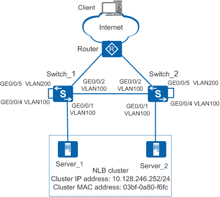
Switch_1 is the master and Switch_2 is the backup. GE0/0/1 interfaces on Switch_1 and Switch_2 are directly connected to two NLB servers respectively. The NLB cluster works in multicast mode, the cluster IP address is 10.128.246.252/24, and the cluster MAC address is 03bf-0a80-f6fc. There are reachable routes between the Switch and Client.
The customer requires that the VRRP group be able to send the Client's packets destined for the NLB cluster IP address to all NLB servers.
Configuration Roadmap
The configuration roadmap is as follows:
- Add GE0/0/1 to VLAN 100.
- Add GE0/0/2 to VLAN 100.
- Disable STP, RSTP, VBST, or MSTP on GE0/0/4 and GE0/0/5, and add the interfaces to VLAN 100 and VLAN 200 respectively in access mode.
- Configure a VRRP virtual IP address for VLANIF 200 that functions as the NLB cluster's gateway.
- Configure a static ARP entry. In the static ARP entry, the IP address is the cluster IP address, the MAC address is the cluster multicast MAC address, and the outbound interface is the interface where the VLAN to which the NLB cluster's gateway belongs is configured.
- Connect GE0/0/4 and GE0/0/5.
Procedure
- # Configure GE0/0/1.
# Add GE0/0/1 on Switch_1 to VLAN 100.
<HUAWEI> system-view
[HUAWEI] sysname Switch_1
[Switch_1] vlan batch 100 200
[Switch_1] interface gigabitethernet 0/0/1
[Switch_1-GigabitEthernet0/0/1] port link-type access
[Switch_1-GigabitEthernet0/0/1] port default vlan 100
[Switch_1-GigabitEthernet0/0/1] quit
# Add GE0/0/1 on Switch_2 to VLAN 100.
<HUAWEI> system-view
[HUAWEI] sysname Switch_2
[Switch_2] vlan batch 100 200
[Switch_2] interface gigabitethernet 0/0/1
[Switch_2-GigabitEthernet0/0/1] port link-type access
[Switch_2-GigabitEthernet0/0/1] port default vlan 100
[Switch_2-GigabitEthernet0/0/1] quit
- Add GE0/0/2 to VLAN 100.
# Add GE0/0/2 on Switch_1 to VLAN 100.
[Switch_1] interface gigabitethernet 0/0/2
[Switch_1-GigabitEthernet0/0/2] port link-type trunk
[Switch_1-GigabitEthernet0/0/2] port trunk allow-pass vlan 100
[Switch_1-GigabitEthernet0/0/2] quit
# Add GE0/0/2 on Switch_2 to VLAN 100.
[Switch_2] interface gigabitethernet 0/0/2
[Switch_2-GigabitEthernet0/0/2] port link-type trunk
[Switch_2-GigabitEthernet0/0/2] port trunk allow-pass vlan 100
[Switch_2-GigabitEthernet0/0/2] quit

Heartbeat interfaces cannot belong to the same VLAN as the gateway to prevent a traffic loop within the VRRP group. For example, GE0/0/2 in this example cannot be added to VLAN 200.
- Configure GE0/0/4 and GE0/0/5.
# Disable STP, RSTP, VBST, or MSTP on GE0/0/4 and GE0/0/5 on Switch_1.
[Switch_1] interface gigabitethernet 0/0/4
[Switch_1-GigabitEthernet0/0/4] undo stp enable
[Switch_1-GigabitEthernet0/0/4] quit
[Switch_1] interface gigabitethernet 0/0/5
[Switch_1-GigabitEthernet0/0/5] undo stp enable
[Switch_1-GigabitEthernet0/0/5] quit
# Add GE0/0/4 and GE0/0/5 on Switch_1 to VLAN 100 and VLAN 200 respectively in access mode.
[Switch_1] interface gigabitethernet 0/0/4
[Switch_1-GigabitEthernet0/0/4] port link-type access
[Switch_1-GigabitEthernet0/0/4] port default vlan 100
[Switch_1-GigabitEthernet0/0/4] quit
[Switch_1] interface gigabitethernet 0/0/5
[Switch_1-GigabitEthernet0/0/5] port link-type access
[Switch_1-GigabitEthernet0/0/5] port default vlan 200
[Switch_1-GigabitEthernet0/0/5] quit
# Disable STP, RSTP, VBST, or MSTP on GE0/0/4 and GE0/0/5 on Switch_2.
[Switch_2] interface gigabitethernet 0/0/4
[Switch_2-GigabitEthernet0/0/4] undo stp enable
[Switch_2-GigabitEthernet0/0/4] quit
[Switch_2] interface gigabitethernet 0/0/5
[Switch_2-GigabitEthernet0/0/5] undo stp enable
[Switch_2-GigabitEthernet0/0/5] quit
# Add GE0/0/4 and GE0/0/5 on Switch_2 to VLAN 100 and VLAN 200 respectively in access mode.
[Switch_2] interface gigabitethernet 0/0/4
[Switch_2-GigabitEthernet0/0/4] port link-type access
[Switch_2-GigabitEthernet0/0/4] port default vlan 100
[Switch_2-GigabitEthernet0/0/4] quit
[Switch_2] interface gigabitethernet 0/0/5
[Switch_2-GigabitEthernet0/0/5] port link-type access
[Switch_2-GigabitEthernet0/0/5] port default vlan 200
[Switch_2-GigabitEthernet0/0/5] quit
- Configure an IP address for the NLB cluster's gateway.
# Create VRRP group 1 on Switch_1 and set the VRRP priority to 120.
[Switch_1] interface vlanif 200
[Switch_1-Vlanif200] ip address 10.128.246.10 24
[Switch_1-Vlanif200] vrrp vrid 1 virtual-ip 10.128.246.250
[Switch_1-Vlanif200] vrrp vrid 1 priority 120
[Switch_1-Vlanif200] quit
# Create VRRP group 1 on Switch_2 and use the default VRRP priority 100.
[Switch_2] interface vlanif 200
[Switch_2-Vlanif200] ip address 10.128.246.11 24
[Switch_2-Vlanif200] vrrp vrid 1 virtual-ip 10.128.246.250
[Switch_2-Vlanif200] quit
- Configure the VRRP virtual IP address 10.128.246.250 for VLANIF 200 that functions as the NLB cluster's gateway.
To reduce network workload, you are advised to separate the NLB cluster's gateway from other gateways.
In this networking, traffic from a switch to the NLB cluster passes along the heartbeat link to the peer switch and then passes along the self-loop line on the peer switch. In this case, if other servers use the same gateway as the NLB servers, other servers will receive traffic destined for the NLB cluster, causing an increase of network workload. For example, packets destined for the NLB cluster from Switch_1 pass along the heartbeat link to Switch_2. On Switch_2, packets are sent from GE0/0/4 to GE0/0/5. If VLANIF 200 on Switch_2 is also the gateway of non-NLB servers, packets are sent to non-NLB servers through GE0/0/5.
- Configure static ARP entries.
# On Switch_1, configure a static ARP entry. In the ARP entry, the IP address is 10.128.246.252, the MAC address is 03bf-0a80-f6fc, the outbound interface is GE0/0/5 where VLAN 200 is located.
[Switch_1] arp static 10.128.246.252 03bf-0a80-f6fc vid 200 interface gigabitethernet 0/0/5
# On Switch_2, configure a static ARP entry. In the ARP entry, the IP address is 10.128.246.252, the MAC address is 03bf-0a80-f6fc, the outbound interface is GE0/0/5 where VLAN 200 is located.
[Switch_2] arp static 10.128.246.252 03bf-0a80-f6fc vid 200 interface gigabitethernet 0/0/5
- Connect GE0/0/4 and GE0/0/5.
After the previous configurations, connect physical links on Switch_1 and Switch_2 respectively.
- Verify the configuration.
Verify that Server_1 and Server_2 can receive packets destined for the NLB cluster.
Configuration Files
Switch_1 configuration file
#
sysname Switch_1
#
vlan batch 100 200
#
interface Vlanif200
 ip address 10.128.246.10 255.255.255.0
 vrrp vrid 1 virtual-ip 10.128.246.250
 vrrp vrid 1 priority 120
#
interface GigabitEthernet0/0/1
 port link-type access
 port default vlan 100
#
interface GigabitEthernet0/0/2
 port link-type trunk
 port trunk allow-pass vlan 100
#
interface GigabitEthernet0/0/4
 port link-type access
 port default vlan 100
 stp disable
#
interface GigabitEthernet0/0/5
 port link-type access
 port default vlan 200
 stp disable
#
arp static 10.128.246.252 03bf-0a80-f6fc vid 200 interface GigabitEthernet0/0/5
#
return
Switch_2 configuration file
#
sysname Switch_2
#
vlan batch 100 200
#
interface Vlanif200
 ip address 10.128.246.11 255.255.255.0
 vrrp vrid 1 virtual-ip 10.128.246.250
#
interface GigabitEthernet0/0/1
 port link-type access
 port default vlan 100
#
interface GigabitEthernet0/0/2
 port link-type trunk
 port trunk allow-pass vlan 100
#
interface GigabitEthernet0/0/4
 port link-type access
 port default vlan 100
 stp disable
#
interface GigabitEthernet0/0/5
 port link-type access
 port default vlan 200
 stp disable
#
arp static 10.128.246.252 03bf-0a80-f6fc vid 200 interface GigabitEthernet0/0/5
#
return