Example for Configuring Egress ARP Inspection
Networking Requirements
In Figure 1, Switch_2 connects to Switch_1 (DHCP server) through GE0/0/3, and connects to Host_1 and Host_2 through GE0/0/1 and GE0/0/2 respectively.
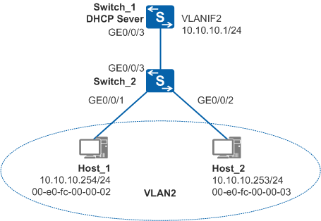
Host_1 and Host_2 obtain IP addresses using DHCP. GE0/0/3 on Switch_1 belongs to the same VLAN (VLAN 2) as GE0/0/1, GE0/0/2, and GE0/0/3 on Switch_2.
- Layer 2 isolation and Layer 3 interworking should be implemented between Host_1 and Host_2 in VLAN 2.
- Switch_2 should not broadcast ARP Request packets in the VLAN to reduce the intra-VLAN network load.
Configuration Roadmap
The configuration roadmap is as follows:
Configure port isolation on GE0/0/1 and GE0/0/2 of Switch_2, and enable intra-VLAN proxy ARP on Switch_1 to implement isolation at Layer 2 and interworking at Layer 3 between Host_1 and Host_2.
Configure DHCP snooping and enable EAI on Switch_2. Switch_2 then can match the destination IP address of an ARP Request packet with the DHCP snooping dynamic binding table to determine the packet's outbound interface, preventing the intra-VLAN packet broadcast.
Enable Switch_2 to forward ARP packets after port isolation is configured, so that Host_1 and Host_2 are isolated at Layer 2 and can communicate at Layer 3 when EAI is configured.
Procedure
- On Switch_1, create a VLAN, add interfaces to the VLAN, and configure the DHCP server function.
# Create VLAN 2 and add GE0/0/3 to VLAN 2.
<HUAWEI> system-view
[HUAWEI] sysname Switch_1
[Switch_1] vlan batch 2
[Switch_1] interface gigabitethernet 0/0/3
[Switch_1-GigabitEthernet0/0/3] port link-type trunk
[Switch_1-GigabitEthernet0/0/3] port trunk allow-pass vlan 2
[Switch_1-GigabitEthernet0/0/3] quit
# Create VLANIF 2, configure an IP address for VLANIF 2, and enable the DHCP server function on VLANIF 2.
[Switch_1] dhcp enable
[Switch_1] interface vlanif 2
[Switch_1-Vlanif2] ip address 10.10.10.1 24
[Switch_1-Vlanif2] dhcp select interface
- On Switch_2, create a VLAN and add interfaces to the VLAN.
# Create VLAN 2, and add GE0/0/1, GE0/0/2, and GE0/0/3 to VLAN 2.
<HUAWEI> system-view
[HUAWEI] sysname Switch_2
[Switch_2] vlan batch 2
[Switch_2] interface gigabitethernet 0/0/1
[Switch_2-GigabitEthernet0/0/1] port link-type access
[Switch_2-GigabitEthernet0/0/1] port default vlan 2
[Switch_2-GigabitEthernet0/0/1] quit
[Switch_2] interface gigabitethernet 0/0/2
[Switch_2-GigabitEthernet0/0/2] port link-type access
[Switch_2-GigabitEthernet0/0/2] port default vlan 2
[Switch_2-GigabitEthernet0/0/2] quit
[Switch_2] interface gigabitethernet 0/0/3
[Switch_2-GigabitEthernet0/0/3] port link-type trunk
[Switch_2-GigabitEthernet0/0/3] port trunk allow-pass vlan 2
[Switch_2-GigabitEthernet0/0/3] quit
- Configure DHCP snooping on Switch_2.
# Enable DHCP snooping globally and in VLAN 2.
[Switch_2] dhcp enable
[Switch_2] dhcp snooping enable
[Switch_2] vlan 2
[Switch_2-vlan2] dhcp snooping enable
[Switch_2-vlan2] quit
# Configure GE0/0/3 as a trusted interface.
[Switch_2] interface gigabitethernet 0/0/3
[Switch_2-GigabitEthernet0/0/3] dhcp snooping trusted
[Switch_2-GigabitEthernet0/0/3] quit
After the configurations, Host_1 and Host_2 functioning as DHCP clients can go online and ping each other, and Switch_2 generates the DHCP snooping dynamic binding table.
- Configure port isolation on Switch_2.
# Configure isolation at Layer 2 and interworking at Layer 3, and configure port isolation between GE0/0/1 and GE0/0/2.
[Switch_2] port-isolate mode l2
[Switch_2] interface gigabitethernet 0/0/1
[Switch_2-GigabitEthernet0/0/1] port-isolate enable
[Switch_2-GigabitEthernet0/0/1] quit
[Switch_2] interface gigabitethernet 0/0/2
[Switch_2-GigabitEthernet0/0/2] port-isolate enable
[Switch_2-GigabitEthernet0/0/2] quit
After the configurations, Host_1 and Host_2 cannot ping each other, indicating that they have been isolated at Layer 2.
- Enable intra-VLAN proxy ARP on Switch_1.
# Enable intra-VLAN proxy ARP on VLANIF 2.
[Switch_1-Vlanif2] arp-proxy inner-sub-vlan-proxy enable
[Switch_1-Vlanif2] quit
After the configurations, Host_1 and Host_2 can ping each other, indicating that they can communicate at Layer 3.
- Enable EAI on Switch_2.
# Enable EAI in VLAN 2.
[Switch_2] vlan 2
[Switch_2-vlan2] dhcp snooping arp security enable
After EAI is enabled and the ARP entry mapping Host_2 on Host_1 has been aged, Host_1 sends an ARP Request packet before it pings Host_2.
As EAI is enabled, Switch_2 matches the destination IP address of the ARP Request packet with the DHCP snooping dynamic binding table to determine the packet's outbound interface. Switch_2 forwards the ARP Request packet to GE0/0/2. As a result, intra-VLAN proxy ARP triggered when the ARP packet reaches Switch_1 through GE0/0/3 cannot take effect. The outbound interface GE0/0/2 determined through EAI has been isolated from the packet's inbound interface GE0/0/1. Therefore, Switch_2 discards the ARP Request packet and Host_1 fails to learn the ARP entry.
At this time, Host_1 and Host_2 cannot ping each other.
- Enable Switch_2 to forward ARP packets when port isolation is configured.
# Enable Switch_2 to forward ARP packets in VLAN 2 when port isolation is configured.
[Switch_2-vlan2] dhcp snooping arp security isolate-forwarding-trust
[Switch_2-vlan2] quit
After the configuration, Switch_2 directly forwards the ARP Request packet from Host_1 to the trusted interface GE0/0/3. As intra-VLAN proxy ARP is configured on Switch_1, Host_1 and Host_2 can ping each other, indicating that Switch_2 has been enabled to forward ARP packets when port isolation is configured.
- Verify the configuration.
Host_1 and Host_2 can ping each other.
Configuration Files
Switch_1 configuration file
#
sysname Switch_1
#
vlan batch 2
#
dhcp enable
#
interface Vlanif2
 ip address 10.10.10.1 255.255.255.0
 arp-proxy inner-sub-vlan-proxy enable
 dhcp select interface
#
interface GigabitEthernet0/0/3
 port link-type trunk
 port trunk allow-pass vlan 2
#
return
Switch_2 configuration file
#
sysname Switch_2
#
vlan batch 2
#
dhcp enable
#
dhcp snooping enable
#
vlan 2
 dhcp snooping enable
 dhcp snooping arp security enable
 dhcp snooping arp security isolate-forwarding-trust
#
interface GigabitEthernet0/0/1
 port link-type access
 port default vlan 2
 port-isolate enable group 1
#
interface GigabitEthernet0/0/2
 port link-type access
 port default vlan 2
 port-isolate enable group 1
#
interface GigabitEthernet0/0/3
 port link-type trunk
 port trunk allow-pass vlan 2
 dhcp snooping trusted
#
return