Example for Configuring Basic MBGP Functions
Networking Requirements
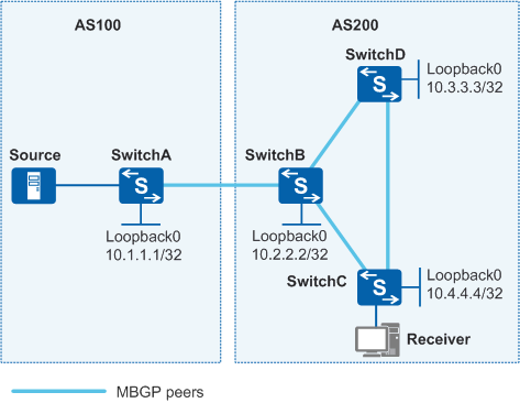
As shown in Figure 1, the receiver receives VoD information in multicast mode. The receiver and the source reside in different ASs. Multicast routing information needs to be transmitted between ASs.

In this scenario, ensure that all connected interfaces have STP disabled. If STP is enabled and VLANIF interfaces of switches are used to construct a Layer 3 ring network, an interface on the network will be blocked. As a result, Layer 3 services on the network cannot run normally.
Data Plan
Link Name (Local End-Remote End) |
Local Interface and IP Address |
Remote Interface and IP Address |
|---|---|---|
SwitchA-SwitchB |
GE0/0/1 VLANIF100:192.168.1.1/24 |
GE0/0/1 VLANIF100:192.168.1.2/24 |
SwitchA-Source |
GE0/0/2 VLANIF101:10.10.10.1/24 |
- |
SwitchB-SwitchD |
GE0/0/2 VLANIF200:192.168.4.2/24 |
GE0/0/2 VLANIF200:192.168.4.1/24 |
SwitchB-SwitchC |
GE0/0/3 VLANIF300:192.168.3.2/24 |
GE0/0/3 VLANIF300:192.168.3.1/24 |
SwitchC-SwitchD |
GE0/0/1 VLANIF400:192.168.5.1/24 |
GE0/0/1 VLANIF400:192.168.5.2/24 |
SwitchC-Receiver |
GE0/0/2 VLANIF102:10.22.22.1/24 |
- |
Configuration Roadmap
The configuration roadmap is as follows:
Configure MBGP peers for inter-AS multicast transmission.
Configure the routes advertised by MBGP.
Enable the multicast function on each switch.
Configure basic PIM-SM functions on each switch in ASs and enable IGMP on receiver-side interfaces.
Configure a BSR boundary on the interfaces that connect to two ASs.
Configure MSDP peers to transmit inter-domain multicast source information.
Procedure
- Configure IP addresses for interfaces on each Switch and the OSPF protocol in
the ASs.
# Configure IP addresses and masks for the interfaces on each switch according to Figure 1 and configure OSPF on the switches in ASs. Ensure that SwitchB, SwitchC, and SwitchD can communicate with the receiver at the network layer, learn routes to the loopback interfaces of each other, and dynamically update routes using a unicast routing protocol. Configure OSPF process 1. The configuration procedure is not mentioned here.
- Configure BGP, enable the MBGP protocol, and configure
the MBGP peers.
# Configure BGP and the MBGP peer on SwitchA.
[SwitchA] bgp 100
[SwitchA-bgp] peer 192.168.1.2 as-number 200
[SwitchA-bgp] ipv4-family multicast
[SwitchA-bgp-af-multicast] peer 192.168.1.2 enable
[SwitchA-bgp-af-multicast] quit
[SwitchA-bgp] quit
# Configure BGP and the MBGP peer on SwitchB.
[SwitchB] bgp 200
[SwitchB-bgp] peer 192.168.1.1 as-number 100
[SwitchB-bgp] peer 192.168.3.1 as-number 200
[SwitchB-bgp] peer 192.168.4.1 as-number 200
[SwitchB-bgp] ipv4-family multicast
[SwitchB-bgp-af-multicast] peer 192.168.1.1 enable
[SwitchB-bgp-af-multicast] peer 192.168.3.1 enable
[SwitchB-bgp-af-multicast] peer 192.168.4.1 enable
[SwitchB-bgp-af-multicast] quit
[SwitchB-bgp] quit
# Configure BGP and the MBGP peer on SwitchC.
[SwitchC] bgp 200
[SwitchC-bgp] peer 192.168.3.2 as-number 200
[SwitchC-bgp] peer 192.168.5.2 as-number 200
[SwitchC-bgp] ipv4-family multicast
[SwitchC-bgp-af-multicast] peer 192.168.3.2 enable
[SwitchC-bgp-af-multicast] peer 192.168.5.2 enable
[SwitchC-bgp-af-multicast] quit
[SwitchC-bgp] quit
# Configure BGP and the MBGP peer on SwitchD.
[SwitchD] bgp 200
[SwitchD-bgp] peer 192.168.4.2 as-number 200
[SwitchD-bgp] peer 192.168.5.1 as-number 200
[SwitchD-bgp] ipv4-family multicast
[SwitchD-bgp-af-multicast] peer 192.168.4.2 enable
[SwitchD-bgp-af-multicast] peer 192.168.5.1 enable
[SwitchD-bgp-af-multicast] quit
[SwitchD-bgp] quit
- Configure the routes to be advertised.
# Configure the routes to be advertised on SwitchA.
[SwitchA] bgp 100
[SwitchA-bgp] import-route direct
[SwitchA-bgp] ipv4-family multicast
[SwitchA-bgp-af-multicast] import-route direct
[SwitchA-bgp-af-multicast] quit
[SwitchA-bgp] quit
# Configure the routes to be advertised on SwitchB.
[SwitchB] bgp 200
[SwitchB-bgp] import-route direct
[SwitchB-bgp] import-route ospf 1
[SwitchB-bgp] ipv4-family multicast
[SwitchB-bgp-af-multicast] import-route direct
[SwitchB-bgp-af-multicast] import-route ospf 1
[SwitchB-bgp-af-multicast] quit
[SwitchB-bgp] quit
- Enable multicast on each Switch and the interfaces that
are connected.
# Configure SwitchA.
[SwitchA] multicast routing-enable
[SwitchA] interface vlanif 100
[SwitchA-Vlanif100] pim sm
[SwitchA-Vlanif100] quit
[SwitchA] interface vlanif 101
[SwitchA-Vlanif101] pim sm
[SwitchA-Vlanif101] quit
# Configure SwitchB.
[SwitchB] multicast routing-enable
[SwitchB] interface vlanif 100
[SwitchB-Vlanif100] pim sm
[SwitchB-Vlanif100] quit
[SwitchB] interface vlanif 200
[SwitchB-Vlanif200] pim sm
[SwitchB-Vlanif200] quit
[SwitchB] interface vlanif 300
[SwitchB-Vlanif300] pim sm
[SwitchB-Vlanif300] quit
# Configure SwitchC.
[SwitchC] multicast routing-enable
[SwitchC] interface vlanif 400
[SwitchC-Vlanif400] pim sm
[SwitchC-Vlanif400] quit
[SwitchC] interface vlanif 102
[SwitchC-Vlanif102] pim sm
[SwitchC-Vlanif102] igmp enable
[SwitchC-Vlanif102] quit
[SwitchC] interface vlanif 300
[SwitchC-Vlanif300] pim sm
[SwitchC-Vlanif300] quit
# Configure SwitchD.
[SwitchD] multicast routing-enable
[SwitchD] interface vlanif 400
[SwitchD-Vlanif400] pim sm
[SwitchD-Vlanif400] quit
[SwitchD] interface vlanif 200
[SwitchD-Vlanif200] pim sm
[SwitchD-Vlanif200] quit
- Configure BSR and RP within each AS.
# Configure SwitchA.
[SwitchA] interface LoopBack 0
[SwitchA-LoopBack0] ip address 10.1.1.1 255.255.255.255
[SwitchA-LoopBack0] pim sm
[SwitchA-LoopBack0] quit
[SwitchA] pim
[SwitchA-pim] c-bsr LoopBack 0
[SwitchA-pim] c-rp LoopBack 0
[SwitchA-pim] quit
# Configure SwitchB.
[SwitchB] interface LoopBack 0
[SwitchB-LoopBack0] ip address 10.2.2.2 255.255.255.255
[SwitchB-LoopBack0] pim sm
[SwitchB-LoopBack0] quit
[SwitchB] pim
[SwitchB-pim] c-bsr LoopBack 0
[SwitchB-pim] c-rp LoopBack 0
[SwitchB-pim] quit
- Configure the BSR boundary on the interfaces connecting
two ASs.
# Configure SwitchA.
[SwitchA] interface vlanif 100
[SwitchA-Vlanif100] pim bsr-boundary
[SwitchA-Vlanif100] quit
# Configure SwitchB.
[SwitchB] interface vlanif 100
[SwitchB-Vlanif100] pim bsr-boundary
[SwitchB-Vlanif100] quit
- Configure MSDP peers.
# Configure SwitchA.
[SwitchA] msdp
[SwitchA-msdp] peer 192.168.1.2 connect-interface Vlanif100
[SwitchA-msdp] quit
# Configure SwitchB.
[SwitchB] msdp
[SwitchB-msdp] peer 192.168.1.1 connect-interface Vlanif100
[SwitchB-msdp] quit
- Verify the configuration.
# Run the display bgp multicast peer command to view the MBGP peer relationship between switches. For example, the following information shows the MBGP peer relationship on SwitchA:
[SwitchA] display bgp multicast peer
BGP local router ID : 10.1.1.1
 Local AS number : 100
 Total number of peers : 1                 Peers in established state : 1
  Peer        V   AS   MsgRcvd  MsgSent  OutQ  Up/Down   State         PrefRcv
  192.168.1.2 4   200  82       75       0     00:30:29  Established    17
# Run the display msdp brief command to view information about the MSDP peer relationship between switches. For example, the following information shows the MBGP peer relationship on SwitchB:
[SwitchB] display msdp brief
MSDP Peer Brief Information
  Configured      Up        Listen       Connect      Shutdown     Down
  1                 1          0             0             0             0

  Peer's Address       State     Up/Down time    AS     SA Count    Reset Count
  192.168.1.1          Up        00:07:17        100     1            0
Configuration Files
SwitchA configuration file
#
sysname SwitchA
#
vlan batch 100 to 101
#
multicast routing-enable
#
interface Vlanif100
 ip address 192.168.1.1 255.255.255.0
 pim bsr-boundary
 pim sm
#
interface Vlanif101
 ip address 10.10.10.1 255.255.255.0
 pim sm
#
interface GigabitEthernet0/0/1
 port link-type trunk
 port trunk allow-pass vlan 100
#
interface GigabitEthernet0/0/2
 port link-type access
 port default vlan 101
#
interface LoopBack0
 ip address 10.1.1.1 255.255.255.255
 pim sm
#
pim
 c-bsr LoopBack0
 c-rp LoopBack0
#
bgp 100
 peer 192.168.1.2 as-number 200
 #
 ipv4-family unicast
  undo synchronization
  import-route direct
  peer 192.168.1.2 enable
 #
 ipv4-family multicast
  undo synchronization
  peer 192.168.1.2 enable
#
msdp
 peer 192.168.1.2 connect-interface Vlanif100
#
return
SwitchB configuration file
#
sysname SwitchB
#
vlan batch 100 200 300
#
multicast routing-enable
#
interface Vlanif100
 ip address 192.168.1.2 255.255.255.0
 pim bsr-boundary
 pim sm
#
interface Vlanif200
 ip address 192.168.4.2 255.255.255.0
 pim sm
#
interface Vlanif300
 ip address 192.168.3.2 255.255.255.0
 pim sm
#
interface GigabitEthernet0/0/1
 port link-type trunk
 port trunk allow-pass vlan 100
#
interface GigabitEthernet0/0/2
 port link-type trunk
 port trunk allow-pass vlan 200
#
interface GigabitEthernet0/0/3
 port link-type trunk
 port trunk allow-pass vlan 300
#
interface LoopBack0
 ip address 10.2.2.2 255.255.255.255
 pim sm
#
pim
 c-bsr LoopBack0
 c-rp LoopBack0
#
ospf 1
 area 0.0.0.0
  network 10.2.2.2 0.0.0.0
  network 192.168.3.0 0.0.0.255
  network 192.168.4.0 0.0.0.255
#
bgp 200
 peer 192.168.1.1 as-number 100
 peer 192.168.3.1 as-number 200
 peer 192.168.4.1 as-number 200
 #
 ipv4-family unicast
  undo synchronization
  import-route direct
  import-route ospf 1
  peer 192.168.1.1 enable
  peer 192.168.3.1 enable
  peer 192.168.4.1 enable
 #
 ipv4-family multicast
  undo synchronization
  import-route direct
  import-route ospf 1
  peer 192.168.1.1 enable
  peer 192.168.3.1 enable
  peer 192.168.4.1 enable
#
msdp
 peer 192.168.1.1 connect-interface Vlanif100
#
return
SwitchC configuration file
#
sysname SwitchC
#
vlan batch 102 300 400
#
multicast routing-enable
#
interface Vlanif102
 ip address 10.22.22.1 255.255.255.0
 pim sm
 igmp enable
#
interface Vlanif300
 ip address 192.168.3.1 255.255.255.0
 pim sm
#
interface Vlanif400
 ip address 192.168.5.1 255.255.255.0
 pim sm
#
interface GigabitEthernet0/0/1
 port link-type trunk
 port trunk allow-pass vlan 400
#
interface GigabitEthernet0/0/2
 port link-type access
 port default vlan 102
#
interface GigabitEthernet0/0/3
 port link-type trunk
 port trunk allow-pass vlan 300
#
interface LoopBack0
 ip address 10.3.3.3 255.255.255.255
#
ospf 1
 area 0.0.0.0
  network 10.3.3.3 0.0.0.0
  network 10.22.22.0 0.0.0.255
  network 192.168.3.0 0.0.0.255
  network 192.168.5.0 0.0.0.255
#
bgp 200
 peer 192.168.3.2 as-number 200
 peer 192.168.5.2 as-number 200
 #
 ipv4-family unicast
  undo synchronization
  peer 192.168.3.2 enable
  peer 192.168.5.2 enable
 #
 ipv4-family multicast
  undo synchronization
  peer 192.168.3.2 enable
  peer 192.168.5.2 enable
#
return
SwitchD configuration file
#
sysname SwitchD
#
vlan batch 200 400
#
multicast routing-enable
#
interface Vlanif200
 ip address 192.168.4.1 255.255.255.0
 pim sm
#
interface Vlanif400
 ip address 192.168.5.2 255.255.255.0
 pim sm
#
interface GigabitEthernet0/0/1
 port link-type trunk
 port trunk allow-pass vlan 400
#
interface GigabitEthernet0/0/2
 port link-type trunk
 port trunk allow-pass vlan 200
#
interface LoopBack0
 ip address 10.4.4.4 255.255.255.255
#
ospf 1
 area 0.0.0.0
  network 10.4.4.4 0.0.0.0
  network 192.168.4.0 0.0.0.255
  network 192.168.5.0 0.0.0.255
#
bgp 200
 peer 192.168.4.2 as-number 200
 peer 192.168.5.1 as-number 200
 #
 ipv4-family unicast
  undo synchronization
  peer 192.168.4.2 enable
  peer 192.168.5.1 enable
 #
 ipv4-family multicast
  undo synchronization
  peer 192.168.4.2 enable
  peer 192.168.5.1 enable
#
return