Example for Configuring BGP to Interact with an IGP
Networking Requirements
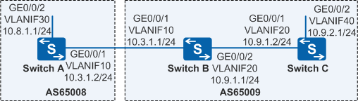
The network shown in Figure 1 is divided into AS 65008 and AS 65009. In AS 65009, an IGP is used to calculate routes. In this example, OSPF is used as an IGP. The two ASs need to communicate with each other.
Configuration Roadmap
The configuration roadmap is as follows:
- Configure OSPF on SwitchB and SwitchC so that these devices can access each other.
- Establish an EBGP connection between SwitchA and SwitchB so that these devices can exchange routing information.
- Configure BGP and OSPF to import routes from each other on SwitchB so that the two ASs can communicate with each other.
- (Optional) Configure BGP route summarization on SwitchB to simplify the BGP routing table.
Procedure
- Create VLANs and add interfaces to the corresponding VLANs.
# Configure SwitchA. The configurations of SwitchB and SwitchC are similar to the configuration of SwitchA.
<HUAWEI> system-view
[HUAWEI] sysname SwitchA
[SwitchA] vlan batch 10 30
[SwitchA] interface gigabitethernet 0/0/1
[SwitchA-GigabitEthernet0/0/1] port link-type trunk
[SwitchA-GigabitEthernet0/0/1] port trunk allow-pass vlan 10
[SwitchA-GigabitEthernet0/0/1] quit
[SwitchA] interface gigabitethernet 0/0/2
[SwitchA-GigabitEthernet0/0/2] port link-type trunk
[SwitchA-GigabitEthernet0/0/2] port trunk allow-pass vlan 30
[SwitchA-GigabitEthernet0/0/2] quit
- Assign an IP address to each VLANIF interface.
# Configure SwitchA. The configurations of SwitchB and SwitchC are similar to the configuration of SwitchA.
[SwitchA] interface vlanif 10
[SwitchA-Vlanif10] ip address 10.3.1.2 24
[SwitchA-Vlanif10] quit
[SwitchA] interface vlanif 30
[SwitchA-Vlanif30] ip address 10.8.1.1 24
[SwitchA-Vlanif30] quit
- Configure OSPF.
# Configure SwitchB.
[SwitchB] ospf 1
[SwitchB-ospf-1] area 0
[SwitchB-ospf-1-area-0.0.0.0] network 10.9.1.0 0.0.0.255
[SwitchB-ospf-1-area-0.0.0.0] quit
[SwitchB-ospf-1] quit
# Configure SwitchC.
[SwitchC] ospf 1
[SwitchC-ospf-1] area 0
[SwitchC-ospf-1-area-0.0.0.0] network 10.9.1.0 0.0.0.255
[SwitchC-ospf-1-area-0.0.0.0] network 10.9.2.0 0.0.0.255
[SwitchC-ospf-1-area-0.0.0.0] quit
[SwitchC-ospf-1] quit
- Configure an EBGP connection.
# Configure SwitchA.
[SwitchA] bgp 65008
[SwitchA-bgp] router-id 10.1.1.1
[SwitchA-bgp] peer 10.3.1.1 as-number 65009
[SwitchA-bgp] ipv4-family unicast
[SwitchA-bgp-af-ipv4] network 10.8.1.0 255.255.255.0
[SwitchA-bgp-af-ipv4] quit
[SwitchA-bgp] quit
# Configure SwitchB.
[SwitchB] bgp 65009
[SwitchB-bgp] router-id 10.2.2.2
[SwitchB-bgp] peer 10.3.1.2 as-number 65008
- Configure BGP to interact with an IGP.
# On SwitchB, configure BGP to import OSPF routes.
[SwitchB-bgp] ipv4-family unicast
[SwitchB-bgp-af-ipv4] import-route ospf 1
[SwitchB-bgp-af-ipv4] quit
[SwitchB-bgp] quit
# Check the routing table of SwitchA.
[SwitchA] display bgp routing-table

 BGP Local router ID is 10.1.1.1
 Status codes: * - valid, > - best, d - damped,
               h - history,  i - internal, s - suppressed, S - Stale
               Origin : i - IGP, e - EGP, ? - incomplete


 Total Number of Routes: 3
      Network            NextHop        MED        LocPrf    PrefVal Path/Ogn

 *>   10.8.1.0/24        0.0.0.0         0                     0      i
 *>   10.9.1.0/24        10.3.1.1        0                     0      65009?
 *>   10.9.2.0/24        10.3.1.1        2                     0      65009?
# On SwitchB, configure OSPF to import BGP routes.
[SwitchB] ospf
[SwitchB-ospf-1] import-route bgp
[SwitchB-ospf-1] quit
# Check the routing table of SwitchC.
[SwitchC] display ip routing-table
Route Flags: R - relay, D - download to fib, T - to vpn-instance
------------------------------------------------------------------------------
Routing Tables: Public
         Destinations : 7        Routes : 7

Destination/Mask    Proto   Pre  Cost      Flags NextHop         Interface

       10.8.1.0/24  O_ASE   150  1           D   10.9.1.1        Vlanif20
       10.9.1.0/24  Direct  0    0           D   10.9.1.2        Vlanif20
       10.9.1.2/32  Direct  0    0           D   127.0.0.1       Vlanif20
       10.9.2.0/24  Direct  0    0           D   10.9.2.1        Vlanif40
       10.9.2.1/32  Direct  0    0           D   127.0.0.1       Vlanif40
      127.0.0.0/8   Direct  0    0           D   127.0.0.1       InLoopBack0
      127.0.0.1/32  Direct  0    0           D   127.0.0.1       InLoopBack0
- Configure automatic summarization.
# Configure SwitchB.
[SwitchB] bgp 65009
[SwitchB-bgp] ipv4-family unicast
[SwitchB-bgp-af-ipv4] summary automatic
[SwitchB-bgp-af-ipv4]  quit
[SwitchB-bgp] quit
# Check the BGP routing table of SwitchA.
[SwitchA] display bgp routing-table

 BGP Local router ID is 10.1.1.1
 Status codes: * - valid, > - best, d - damped,
               h - history,  i - internal, s - suppressed, S - Stale
               Origin : i - IGP, e - EGP, ? - incomplete


 Total Number of Routes: 2
      Network            NextHop        MED        LocPrf    PrefVal Path/Ogn

 *>   10.0.0.0           10.3.1.1                              0      65009?
 *>   10.8.1.0/24        0.0.0.0         0                     0      i
# Perform the ping operation to verify the configuration.
[SwitchA] ping -a 10.8.1.1 10.9.2.1
  PING 10.9.2.1: 56  data bytes, press CTRL_C to break
    Reply from 10.9.2.1: bytes=56 Sequence=1 ttl=253 time=15 ms
    Reply from 10.9.2.1: bytes=56 Sequence=2 ttl=253 time=31 ms
    Reply from 10.9.2.1: bytes=56 Sequence=3 ttl=253 time=47 ms
    Reply from 10.9.2.1: bytes=56 Sequence=4 ttl=253 time=46 ms
    Reply from 10.9.2.1: bytes=56 Sequence=5 ttl=253 time=47 ms

  --- 10.9.2.1 ping statistics ---
    5 packet(s) transmitted
    5 packet(s) received
    0.00% packet loss
    round-trip min/avg/max = 15/37/47 ms
Configuration Files
SwitchA configuration file
#
sysname SwitchA
#
vlan batch 10 30
#
interface Vlanif10
 ip address 10.3.1.2 255.255.255.0
#
interface Vlanif30
 ip address 10.8.1.1 255.255.255.0
#
interface GigabitEthernet0/0/1
 port link-type trunk
 port trunk allow-pass vlan 10
#
interface GigabitEthernet0/0/2
 port link-type trunk
 port trunk allow-pass vlan 30
#
bgp 65008
 router-id 10.1.1.1
 peer 10.3.1.1 as-number 65009
 #
 ipv4-family unicast
  undo synchronization
  network 10.8.1.0 255.255.255.0
  peer 10.3.1.1 enable
#
return
SwitchB configuration file
#
sysname SwitchB
#
vlan batch 10 20
#
interface Vlanif10
 ip address 10.3.1.1 255.255.255.0
#
interface Vlanif20
 ip address 10.9.1.1 255.255.255.0
#
interface GigabitEthernet0/0/1
 port link-type trunk
 port trunk allow-pass vlan 10
#
interface GigabitEthernet0/0/2
 port link-type trunk
 port trunk allow-pass vlan 20
#
bgp 65009
 router-id 10.2.2.2
 peer 10.3.1.2 as-number 65008
 #
 ipv4-family unicast
  undo synchronization
  summary automatic
  import-route ospf 1
  peer 10.3.1.2 enable
#
ospf 1
 import-route bgp
 area 0.0.0.0
  network 10.9.1.0 0.0.0.255
#
return
SwitchC configuration file
#
sysname SwitchC
#
vlan batch 20 40
#
interface Vlanif20
 ip address 10.9.1.2 255.255.255.0
#
interface Vlanif40
 ip address 10.9.2.1 255.255.255.0
#
interface GigabitEthernet0/0/1
 port link-type trunk
 port trunk allow-pass vlan 20
#
interface GigabitEthernet0/0/2
 port link-type trunk
 port trunk allow-pass vlan 40
#
ospf 1
 area 0.0.0.0
  network 10.9.1.0 0.0.0.255
  network 10.9.2.0 0.0.0.255
#
return