Example for Configuring the BGP Community Attribute
Networking Requirements
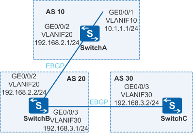
As shown in Figure 1, EBGP connections are established between SwitchB and SwitchA, and between SwitchB and SwitchC. It is required that AS 20 not advertise the routes advertised by AS 10 to AS 30.
Configuration Roadmap
The configuration roadmap is as follows:
Configure a route-policy on SwitchA to advertise the No_Export attribute so that AS 20 does not advertise the routes advertised by AS 10 to AS 30.
Procedure
- Configure the VLAN to which each interface belongs.
# Configure SwitchA. The configurations of SwitchB and SwitchC are similar to the configuration of SwitchA.
<HUAWEI> system-view
[HUAWEI] sysname SwitchA
[SwitchA] vlan batch 10 20
[SwitchA] interface gigabitethernet 0/0/1
[SwitchA-GigabitEthernet0/0/1] port link-type trunk
[SwitchA-GigabitEthernet0/0/1] port trunk allow-pass vlan 10
[SwitchA-GigabitEthernet0/0/1] quit
[SwitchA] interface gigabitethernet 0/0/2
[SwitchA-GigabitEthernet0/0/2] port link-type trunk
[SwitchA-GigabitEthernet0/0/2] port trunk allow-pass vlan 20
[SwitchA-GigabitEthernet0/0/2] quit
- Assign an IP address to each VLANIF interface.
# Configure SwitchA. The configurations of SwitchB and SwitchC are similar to the configuration of SwitchA.
[SwitchA] interface vlanif 10
[SwitchA-Vlanif10] ip address 10.1.1.1 24
[SwitchA-Vlanif10] quit
[SwitchA] interface vlanif 20
[SwitchA-Vlanif20] ip address 192.168.2.1 24
[SwitchA-Vlanif20] quit
- Configure EBGP.
# ConfigureSwitchA.
[SwitchA] bgp 10
[SwitchA-bgp] router-id 172.16.1.1
[SwitchA-bgp] peer 192.168.2.2 as-number 20
[SwitchA-bgp] ipv4-family unicast
[SwitchA-bgp-af-ipv4] network 10.1.1.0 255.255.255.0
[SwitchA-bgp-af-ipv4] quit
[SwitchA-bgp] quit
# Configure SwitchB.
[SwitchB] bgp 20
[SwitchB-bgp] router-id 172.16.2.2
[SwitchB-bgp] peer 192.168.2.1 as-number 10
[SwitchB-bgp] peer 192.168.3.2 as-number 30
[SwitchB-bgp] quit
# Configure SwitchC.
[SwitchC] bgp 30
[SwitchC-bgp] router-id 172.16.3.3
[SwitchC-bgp] peer 192.168.3.1 as-number 20
[SwitchC-bgp] quit
# Check the routing table of SwitchB.
[SwitchB] display bgp routing-table 10.1.1.0

BGP local router ID : 172.16.2.2
 Local AS number : 20
 Paths:   1 available, 1 best, 1 select
 BGP routing table entry information of 10.1.1.0/24:
 From: 192.168.2.1 (172.16.1.1)
 Route Duration: 00h00m15s
 Direct Out-interface: Vlanif20
 Original nexthop: 192.168.2.1
 Qos information : 0x0
 AS-path 10, origin igp, MED 0, pref-val 0, valid, external, best, select, active, pre 255
 Advertised to such 2 peers:
    192.168.2.1
    192.168.3.2
You can view that SwitchB advertises the received routes to SwitchC in AS 30.
# Check the routing table of SwitchC.
[SwitchC] display bgp routing-table

 BGP Local router ID is 172.16.3.3
 Status codes: * - valid, > - best, d - damped,
               h - history,  i - internal, s - suppressed, S - Stale
               Origin : i - IGP, e - EGP, ? - incomplete
 Total Number of Routes: 1
      Network            NextHop        MED        LocPrf    PrefVal Path/Ogn

 *>   10.1.1.0/24        192.168.3.1                           0      20 10i
You can find that SwitchC has learned a route to the destination 10.1.1.0/24 from SwitchB.
- Configure BGP community attributes.
# Configure the routing policy on SwitchA to enable SwitchB not to advertise the routes advertised by SwitchA to any other AS.
[SwitchA] route-policy comm_policy permit node 10
[SwitchA-route-policy] apply community no-export
[SwitchA-route-policy] quit
# Apply routing policies.
[SwitchA] bgp 10
[SwitchA-bgp] ipv4-family unicast
[SwitchA-bgp-af-ipv4] peer 192.168.2.2 route-policy comm_policy export
[SwitchA-bgp-af-ipv4] peer 192.168.2.2 advertise-community
# Check the routing table of SwitchB.
[SwitchB] display bgp routing-table 10.1.1.0

BGP local router ID : 172.16.2.2
 Local AS number : 20
 Paths:   1 available, 1 best, 1 select
 BGP routing table entry information of 10.1.1.0/24:
 From: 192.168.2.1 (172.16.1.1)
 Route Duration: 00h00m33s
 Direct Out-interface: Vlanif20
 Original nexthop: 192.168.2.1
 Qos information : 0x0
 Community:no-export
 AS-path 10, origin igp, MED 0, pref-val 0, valid, external, best, select, activ
e, pre 255
 Not advertised to any peer yet
You can view the configured community attribute in the BGP routing table of SwitchB. At this time, there are no routes to the destination 10.1.1.0/24 in the BGP routing table of SwitchC.
Configuration Files
SwitchA configuration file
#
sysname SwitchA
#
vlan batch 10 20
#
interface Vlanif10
 ip address 10.1.1.1 255.255.255.0
#
interface Vlanif20
 ip address 192.168.2.1 255.255.255.0
#
interface GigabitEthernet0/0/1
 port link-type trunk
 port trunk allow-pass vlan 10
#
interface GigabitEthernet0/0/2
 port link-type trunk
 port trunk allow-pass vlan 20
#
bgp 10
 router-id 172.16.1.1
 peer 192.168.2.2 as-number 20
 #
 ipv4-family unicast
  undo synchronization
  network 10.1.1.0 255.255.255.0
  peer 192.168.2.2 enable
  peer 192.168.2.2 route-policy comm_policy export
  peer 192.168.2.2 advertise-community
#
route-policy comm_policy permit node 10
 apply community no-export
#
return
SwitchB configuration file
#
sysname SwitchB
#
vlan batch 20 30
#
interface Vlanif20
 ip address 192.168.2.2 255.255.255.0
#
interface Vlanif30
 ip address 192.168.3.1 255.255.255.0
#
interface GigabitEthernet0/0/2
 port link-type trunk
 port trunk allow-pass vlan 20
#
interface GigabitEthernet0/0/3
 port link-type trunk
 port trunk allow-pass vlan 30
#
bgp 20
 router-id 172.16.2.2
 peer 192.168.2.1 as-number 10
 peer 192.168.3.2 as-number 30
 #
 ipv4-family unicast
  undo synchronization
  peer 192.168.2.1 enable
  peer 192.168.3.2 enable
#
return
SwitchC configuration file
#
sysname SwitchC
#
vlan 30
#
interface Vlanif30
 ip address 192.168.3.2 255.255.255.0
#
interface GigabitEthernet0/0/3
 port link-type trunk
 port trunk allow-pass vlan 30
#
bgp 30
 router-id 172.16.3.3
 peer 192.168.3.1 as-number 20
 #
 ipv4-family unicast
  undo synchronization
  peer 192.168.3.1 enable
#
return