Example for Configuring BGP Load Balancing
Networking Requirements
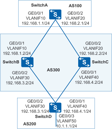
On the network shown in Figure 1, BGP is configured on all switches. SwitchA is in AS 100. SwitchB and SwitchC are in AS 300. SwitchD is in AS 200. Network congestion from SwitchA to destination address 10.1.1.0/24 needs to be relieved and network resources need to be fully utilized.

In this scenario, ensure that all connected interfaces have STP disabled. If STP is enabled and VLANIF interfaces of switches are used to construct a Layer 3 ring network, an interface on the network will be blocked. As a result, Layer 3 services on the network cannot run normally.
Configuration Roadmap
The configuration roadmap is as follows:
Establish EBGP connections between SwitchA and SwitchB and between SwitchA and SwitchC, between SwitchD and SwitchB and between SwitchD and SwitchC to enable ASs to communicate with each other using BGP.
- Configuring load balancing on SwitchA so that SwitchA can send traffic to SwitchD through either SwitchB or SwitchC.
Procedure
- Configure the VLAN to which each interface belongs.
# Configure SwitchA. The configurations of SwitchB, SwitchC, and SwitchD are similar to the configuration of SwitchA.
<HUAWEI> system-view
[HUAWEI] sysname SwitchA
[SwitchA] vlan batch 10 20
[SwitchA] interface gigabitethernet 0/0/1
[SwitchA-GigabitEthernet0/0/1] port link-type trunk
[SwitchA-GigabitEthernet0/0/1] port trunk allow-pass vlan 10
[SwitchA-GigabitEthernet0/0/1] quit
[SwitchA] interface gigabitethernet 0/0/2
[SwitchA-GigabitEthernet0/0/2] port link-type trunk
[SwitchA-GigabitEthernet0/0/2] port trunk allow-pass vlan 20
[SwitchA-GigabitEthernet0/0/2] quit
- Assign an IP address to each VLANIF interface.
# Configure SwitchA. The configurations of SwitchB, SwitchC, and SwitchD are similar to the configuration of SwitchA.
[SwitchA] interface vlanif 10
[SwitchA-Vlanif10] ip address 192.168.1.1 24
[SwitchA-Vlanif10] quit
[SwitchA] interface vlanif 20
[SwitchA-Vlanif20] ip address 192.168.2.1 24
[SwitchA-Vlanif20] quit
- Establish BGP connections.
# Configure RouterA.
[SwitchA] bgp 100
[SwitchA-bgp] router-id 172.16.1.1
[SwitchA-bgp] peer 192.168.1.2 as-number 300
[SwitchA-bgp] peer 192.168.2.2 as-number 300
[SwitchA-bgp] quit
# Configure RouterB.
[SwitchB] bgp 300
[SwitchB-bgp] router-id 172.16.2.2
[SwitchB-bgp] peer 192.168.1.1 as-number 100
[SwitchB-bgp] peer 192.168.3.1 as-number 200
[SwitchB-bgp] quit
# Configure RouterC.
[SwitchC] bgp 300
[SwitchC-bgp] router-id 172.16.3.3
[SwitchC-bgp] peer 192.168.2.1 as-number 100
[SwitchC-bgp] peer 192.168.4.1 as-number 200
[SwitchC-bgp] quit
# Configure RouterD.
[SwitchD] bgp 200
[SwitchD-bgp] router-id 172.16.4.4
[SwitchD-bgp] peer 192.168.3.2 as-number 300
[SwitchD-bgp] peer 192.168.4.2 as-number 300
[SwitchD-bgp] ipv4-family unicast
[SwitchD-bgp-af-ipv4] network 10.1.1.0 255.255.255.0
[SwitchD-bgp-af-ipv4] quit
[SwitchD-bgp] quit
# View the routing table of SwitchA.
[SwitchA] display bgp routing-table 10.1.1.0 24

 BGP local router ID : 172.16.1.1
 Local AS number : 100
 Paths:   2 available, 1 best, 1 select
 BGP routing table entry information of 10.1.1.0/24:
 From: 192.168.1.2 (172.16.2.2)
 Route Duration: 0d00h00m50s
 Direct Out-interface: Vlanif10
 Original nexthop: 192.168.1.2
 Qos information : 0x0
 AS-path 300 200, origin igp, pref-val 0, valid, external, best, select, active, pre 255
 Advertised to such 2 peers:
    192.168.2.2
    192.168.1.2
 BGP routing table entry information of 10.1.1.0/24:
 From: 192.168.2.2 (172.16.3.3)
 Route Duration: 0d00h00m51s
 Direct Out-interface: Vlanif20
 Original nexthop: 192.168.2.2
 Qos information : 0x0
 AS-path 300 200, origin igp, pref-val 0, valid, external, pre 255, not preferred for router ID
 Not advertised to any peer yet
The preceding command output shows that there are two valid routes from SwitchA to destination 10.1.1.0/24. The route with the next-hop address of 192.168.1.2 is the optimal route because the router ID of SwitchB is smaller.
- Configure BGP load balancing.
# Configure load balancing on SwitchA.
[SwitchA] bgp 100
[SwitchA-bgp] ipv4-family unicast
[SwitchA-bgp-af-ipv4] maximum load-balancing 2
[SwitchA-bgp-af-ipv4] quit
[SwitchA-bgp] quit
- Verify the configuration.
# View the routing table of SwitchA.
[SwitchA] display bgp routing-table 10.1.1.0 24

 BGP local router ID : 172.16.1.1
 Local AS number : 100
 Paths:   2 available, 1 best, 2 select
 BGP routing table entry information of 10.1.1.0/24:
 From: 192.168.1.2 (172.16.2.2)
 Route Duration: 0d00h03m55s
 Direct Out-interface: Vlanif10
 Original nexthop: 192.168.1.2
 Qos information : 0x0
 AS-path 300 200, origin igp, pref-val 0, valid, external, best, select, active, pre 255
 Advertised to such 2 peers:
    192.168.2.2
    192.168.1.2

 BGP routing table entry information of 10.1.1.0/24:
 From: 192.168.2.2 (172.16.3.3)
 Route Duration: 0d00h03m56s
 Direct Out-interface: Vlanif20
 Original nexthop: 192.168.2.2
 Qos information : 0x0
 AS-path 300 200, origin igp, pref-val 0, valid, external, select, active, pre 255, not preferred for router ID
 Not advertised to any peer yet
The preceding command output shows that BGP route 10.1.1.0/24 has two next hops: 192.168.1.2 and 192.168.2.2. Both of them are optimal routes.
Configuration Files
SwitchA configuration file
#
sysname SwitchA
#
vlan batch 10 20
#
interface Vlanif10
 ip address 192.168.1.1 255.255.255.0
#
interface Vlanif20
 ip address 192.168.2.1 255.255.255.0
#
interface GigabitEthernet0/0/1
 port link-type trunk
 port trunk allow-pass vlan 10
#
interface GigabitEthernet0/0/2
 port link-type trunk
 port trunk allow-pass vlan 20
#
bgp 100
 router-id 172.16.1.1
 peer 192.168.1.2 as-number 300
 peer 192.168.2.2 as-number 300
 #
 ipv4-family unicast
  undo synchronization
  maximum load-balancing 2
  peer 192.168.1.2 enable
  peer 192.168.2.2 enable
#
return
SwitchB configuration file
#
sysname SwitchB
#
vlan batch 10 30
#
interface Vlanif10
 ip address 192.168.1.2 255.255.255.0
#
interface Vlanif30
 ip address 192.168.3.2 255.255.255.0
#
interface GigabitEthernet0/0/1
 port link-type trunk
 port trunk allow-pass vlan 10
#
interface GigabitEthernet0/0/2
 port link-type trunk
 port trunk allow-pass vlan 30
#
bgp 300
 router-id 172.16.2.2
 peer 192.168.1.1 as-number 100
 peer 192.168.3.1 as-number 200
 #
 ipv4-family unicast
  undo synchronization
  peer 192.168.1.1 enable
  peer 192.168.3.1 enable
#
return
SwitchC configuration file
#
sysname SwitchC
#
vlan batch 20 40
#
interface Vlanif20
 ip address 192.168.2.2 255.255.255.0
#
interface Vlanif40
 ip address 192.168.4.2 255.255.255.0
#
interface GigabitEthernet0/0/1
 port link-type trunk
 port trunk allow-pass vlan 40
#
interface GigabitEthernet0/0/2
 port link-type trunk
 port trunk allow-pass vlan 20
#
bgp 300
 router-id 172.16.3.3
 peer 192.168.2.1 as-number 100
 peer 192.168.4.1 as-number 200
 #
 ipv4-family unicast
  undo synchronization
  peer 192.168.2.1 enable
  peer 192.168.4.1 enable
#
return
SwitchD configuration file
#
sysname SwitchD
#
vlan batch 30 40 50
#
interface Vlanif30
 ip address 192.168.3.1 255.255.255.0
#
interface Vlanif40
 ip address 192.168.4.1 255.255.255.0
#
interface Vlanif50
 ip address 10.1.1.1 255.255.255.0
#
interface GigabitEthernet0/0/1
 port link-type trunk
 port trunk allow-pass vlan 40
#
interface GigabitEthernet0/0/2
 port link-type trunk
 port trunk allow-pass vlan 30
#
interface GigabitEthernet0/0/3
 port link-type trunk
 port trunk allow-pass vlan 50
#
bgp 200
 router-id 172.16.4.4
 peer 192.168.3.2 as-number 300
 peer 192.168.4.2 as-number 300
 #
 ipv4-family unicast
  undo synchronization
  network 10.1.1.0 255.255.255.0
  peer 192.168.3.2 enable
  peer 192.168.4.2 enable
#
return