Example for Configuring BFD for BGP
Networking Requirements
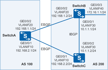
As shown in Figure 1, SwitchA belongs to AS 100, and SwitchB and SwitchC belong to AS 200. EBGP connections are established between SwitchA and SwitchB, and between SwitchA and SwitchC.
Service traffic is transmitted along the primary link SwitchA→SwitchB. The link SwitchA→SwitchC→SwitchB functions as the backup link. Fast fault detection is required to allow traffic to be fast switched from the primary link to the backup link.

In this scenario, ensure that all connected interfaces have STP disabled. If STP is enabled and VLANIF interfaces of switches are used to construct a Layer 3 ring network, an interface on the network will be blocked. As a result, Layer 3 services on the network cannot run normally.
Configuration Roadmap
The configuration roadmap is as follows:
Configure basic BGP functions on each switch.
Configure the MED attribute to control route selection.
Enable BFD on SwitchA and SwitchB.
If two switches establish an EBGP peer relationship over a direct link, BFD for BGP does not need to be configured. This is because the ebgp-interface-sensitive command is enabled by default for directly-connected EBGP peers.
Procedure
- Configure the VLAN to which each interface belongs.
# Configure SwitchA. The configurations of SwitchB and SwitchC are similar to the configuration of SwitchA.
<HUAWEI> system-view
[HUAWEI] sysname SwitchA
[SwitchA] vlan batch 10 20
[SwitchA] interface gigabitethernet 0/0/1
[SwitchA-GigabitEthernet0/0/1] port link-type trunk
[SwitchA-GigabitEthernet0/0/1] port trunk allow-pass vlan 10
[SwitchA-GigabitEthernet0/0/1] quit
[SwitchA] interface gigabitethernet 0/0/2
[SwitchA-GigabitEthernet0/0/2] port link-type trunk
[SwitchA-GigabitEthernet0/0/2] port trunk allow-pass vlan 20
[SwitchA-GigabitEthernet0/0/2] quit
- Assign an IP address to each VLANIF interface.
# Configure SwitchA. The configurations of SwitchB and SwitchC are similar to the configuration of SwitchA.
[SwitchA] interface vlanif 10
[SwitchA-Vlanif10] ip address 192.168.2.1 24
[SwitchA-Vlanif10] quit
[SwitchA] interface vlanif 20
[SwitchA-Vlanif20] ip address 192.168.1.1 24
[SwitchA-Vlanif20] quit
- Configure basic BGP functions. Establish EBGP peer relationships
between SwitchA and SwitchB, and between SwitchA and SwitchC and an IBGP peer relationship
between SwitchB and SwitchC.
# Configure SwitchA.
[SwitchA] bgp 100
[SwitchA-bgp] router-id 172.17.1.1
[SwitchA-bgp] peer 192.168.1.2 as-number 200
[SwitchA-bgp] peer 192.168.1.2 ebgp-max-hop
[SwitchA-bgp] peer 192.168.2.2 as-number 200
[SwitchA-bgp] peer 192.168.2.2 ebgp-max-hop
[SwitchA-bgp] quit
# Configure SwitchB.
[SwitchB] bgp 200
[SwitchB-bgp] router-id 172.17.2.2
[SwitchB-bgp] peer 192.168.1.1 as-number 100
[SwitchB-bgp] peer 192.168.1.1 ebgp-max-hop
[SwitchB-bgp] peer 10.1.1.2 as-number 200
[SwitchB-bgp] network 172.16.1.0 255.255.255.0
[SwitchB-bgp] quit
# Configure SwitchC.
[SwitchC] bgp 200
[SwitchC-bgp] router-id 172.17.3.3
[SwitchC-bgp] peer 192.168.2.1 as-number 100
[SwitchC-bgp] peer 192.168.2.1 ebgp-max-hop
[SwitchC-bgp] peer 10.1.1.1 as-number 200
[SwitchC-bgp] import-route direct
[SwitchC-bgp] quit
# Check the status of BGP peer relationships on SwitchA. The command output shows that the BGP peer relationships are in the Established state.
[SwitchA] display bgp peer BGP local router ID : 172.17.1.1 Local AS number : 100 Total number of peers : 2 Peers in established state : 2 Peer V AS MsgRcvd MsgSent OutQ Up/Down State PrefRcv 192.168.1.2 4 200 2 5 0 00:01:25 Established 0 192.168.2.2 4 200 2 4 0 00:00:55 Established 0 - Set the MED.
Set the MED sent from SwitchB to SwitchC through the policy.
# Configure SwitchB.
[SwitchB] route-policy 10 permit node 10
[SwitchB-route-policy] apply cost 100
[SwitchB-route-policy] quit
[SwitchB] bgp 200
[SwitchB-bgp] peer 192.168.1.1 route-policy 10 export
[SwitchB-bgp] quit
# Configure SwitchC.
[SwitchC] route-policy 10 permit node 10
[SwitchC-route-policy] apply cost 150
[SwitchC-route-policy] quit
[SwitchC] bgp 200
[SwitchC-bgp] peer 192.168.2.1 route-policy 10 export
[SwitchC-bgp] quit
# View all BGP routing information on SwitchA.
[SwitchA] display bgp routing-table

 BGP Local router ID is 172.17.1.1
 Status codes: * - valid, > - best, d - damped,
               h - history,  i - internal, s - suppressed, S - Stale
               Origin : i - IGP, e - EGP, ? - incomplete
 Total Number of Routes: 5

     Network            NextHop        MED        LocPrf    PrefVal Path/Ogn
 *>  10.1.1.0/24        192.168.2.2     150                   0      200?
 *>  172.16.1.0/24      192.168.1.2     100                   0      200i
 *                      192.168.2.2     150                   0      200i
 *>  192.168.2.0        192.168.1.2     100                   0      200?
                        192.168.2.2     150                   0      200?
According to the BGP routing table, the next-hop address of the route destined for 172.16.1.0/24 is 192.168.1.2 and service flow is transmitted on the active link SwitchA → SwitchB.
- Configure BFD, and set the interval for transmitting BFD
packets, the interval for receiving BFD packets, and the local detection
multiplier.
# Enable BFD on SwitchA. Set the minimum intervals for transmitting and receiving BFD packets to 100 ms and the local detection multiplier to 4.
[SwitchA] bfd
[SwitchA-bfd] quit
[SwitchA] bgp 100
[SwitchA-bgp] peer 192.168.1.2 bfd enable
[SwitchA-bgp] peer 192.168.1.2 bfd min-tx-interval 100 min-rx-interval 100 detect-multiplier 4
[SwitchA-bgp] quit
# Enable BFD on SwitchB. Set the minimum intervals for transmitting and receiving BFD packets to 100 ms and the local detection multiplier to 4.
[SwitchB] bfd
[SwitchB-bfd] quit
[SwitchB] bgp 200
[SwitchB-bgp] peer 192.168.1.1 bfd enable
[SwitchB-bgp] peer 192.168.1.1 bfd min-tx-interval 100 min-rx-interval 100 detect-multiplier 4
[SwitchB-bgp] quit
# Display all BFD sessions on SwitchA.
[SwitchA] display bgp bfd session all
  Local_Address      Peer_Address       LD/RD       Interface
  192.168.1.1        192.168.1.2        8201/8201   Vlanif20
  Tx-interval(ms)    Rx-interval(ms)    Multiplier  Session-State
  100                100                4           Up
  Wtr-interval(m)
  0
- Verify the configuration.
# Run the shutdown command on VLANIF20 of SwitchB to simulate faults on the active link.
[SwitchB] interface vlanif 20
[SwitchB-Vlanif20] shutdown
# Check the BGP routing table on SwitchA.
[SwitchA] display bgp routing-table

 BGP Local router ID is 172.17.1.1
 Status codes: * - valid, > - best, d - damped,
               h - history,  i - internal, s - suppressed, S - Stale
               Origin : i - IGP, e - EGP, ? - incomplete
 Total Number of Routes: 3

      Network            NextHop        MED        LocPrf    PrefVal Path/Ogn
 *>  10.1.1.0/24         192.168.2.2     150                   0      200?
 *>  172.16.1.0/24       192.168.2.2     150                   0      200i
     192.168.2.0         192.168.2.2     150                   0      200?
According to the BGP routing table, the standby link SwitchA → SwitchC → SwitchB takes effect after the active link fails. The next-hop address of the route destined for 172.16.1.0/24 becomes 192.168.2.2.
Configuration Files
SwitchA configuration file
#
sysname SwitchA
#
vlan batch 10 20
#
bfd
#
interface Vlanif10
 ip address 192.168.2.1 255.255.255.0
#
interface Vlanif20
 ip address 192.168.1.1 255.255.255.0
#
interface GigabitEthernet0/0/1
 port link-type trunk
 port trunk allow-pass vlan 10
#
interface GigabitEthernet0/0/2
 port link-type trunk
 port trunk allow-pass vlan 20
#
bgp 100
 router-id 172.17.1.1
 peer 192.168.1.2 as-number 200
 peer 192.168.1.2 ebgp-max-hop 255
 peer 192.168.1.2 bfd min-tx-interval 100 min-rx-interval 100 detect-multiplier 4
 peer 192.168.1.2 bfd enable
 peer 192.168.2.2 as-number 200
 peer 192.168.2.2 ebgp-max-hop 255
 #
 ipv4-family unicast
  undo synchronization
  peer 192.168.1.2 enable
  peer 192.168.2.2 enable
#
return
SwitchB configuration file
#
sysname SwitchB
#
vlan batch 20 30 40
#
bfd
#
interface Vlanif20
 ip address 192.168.1.2 255.255.255.0
#
interface Vlanif30
 ip address 10.1.1.1 255.255.255.0
#
interface Vlanif40
 ip address 172.16.1.1 255.255.255.0
#
interface GigabitEthernet0/0/1
 port link-type trunk
 port trunk allow-pass vlan 30
#
interface GigabitEthernet0/0/2
 port link-type trunk
 port trunk allow-pass vlan 20
#
interface GigabitEthernet0/0/3
 port link-type trunk
 port trunk allow-pass vlan 40
#
bgp 200
 router-id 172.17.2.2
 peer 10.1.1.2 as-number 200
 peer 192.168.1.1 as-number 100
 peer 192.168.1.1 ebgp-max-hop 255
 peer 192.168.1.1 bfd min-tx-interval 100 min-rx-interval 100 detect-multiplier 4
 peer 192.168.1.1 bfd enable
 #
 ipv4-family unicast
  undo synchronization
  network 172.16.1.0 255.255.255.0
  peer 10.1.1.2 enable
  peer 192.168.1.1 enable
  peer 192.168.1.1 route-policy 10 export
#
route-policy 10 permit node 10
 apply cost 100
#
return
SwitchC configuration file
#
sysname SwitchC
#
vlan batch 10 30
#
bfd
#
interface Vlanif10
 ip address 192.168.2.2 255.255.255.0
#
interface Vlanif30
 ip address 10.1.1.2 255.255.255.0
#
interface GigabitEthernet0/0/1
 port link-type trunk
 port trunk allow-pass vlan 10
#
interface GigabitEthernet0/0/2
 port link-type trunk
 port trunk allow-pass vlan 30
#
bgp 200
 router-id 172.17.3.3
 peer 10.1.1.1 as-number 200
 peer 192.168.2.1 as-number 100
 peer 192.168.2.1 ebgp-max-hop 255
 #
 ipv4-family unicast
  undo synchronization
  import-route direct
  peer 10.1.1.1 enable
  peer 192.168.2.1 enable
  peer 192.168.2.1 route-policy 10 export
#
route-policy 10 permit node 10
 apply cost 150
#
return