Example for Configuring BFD for BGP4+
Networking Requirements
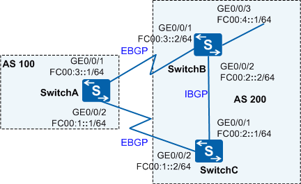
In Figure 1, SwitchA belongs to AS 100, and SwitchB and SwitchC belong to AS 200. SwitchA establishes EBGP connections with both SwitchB and SwitchC.
Service traffic is forwarded along the primary link SwitchA→SwitchB. The link SwitchA→SwitchC→SwitchB is used as a backup. Customers require that a fault on the primary link be detected in milliseconds so that service traffic can be fast switched to the backup link if the primary link fails.

In this scenario, ensure that all connected interfaces have STP disabled. If STP is enabled and VLANIF interfaces of switches are used to construct a Layer 3 ring network, an interface on the network will be blocked. As a result, Layer 3 services on the network cannot run normally.
Configuration Roadmap
The configuration roadmap is as follows:
Configure basic BGP4+ functions on all switches so that they can establish BGP peer relationships with each other.
Configure MED-based route selection on SwitchA and SwitchB to forward traffic on the primary link between SwitchA and SwitchB.
Enable BFD on SwitchA and SwitchB to detect faults in milliseconds so that service traffic can be fast switched to the backup link if the primary link fails.
Procedure
- Enable the IPv6 forwarding capability and configure IPv6
addresses for interfaces.
# Configure SwitchA. The configurations of SwitchB and SwitchC are similar to the configuration of SwitchA.
<HUAWEI> system-view
[HUAWEI] sysname SwitchA
[SwitchA] ipv6
[SwitchA] interface GigabitEthernet 0/0/1
[SwitchA-GigabitEthernet0/0/1] undo portswitch
[SwitchA-GigabitEthernet0/0/1] ipv6 enable
[SwitchA-GigabitEthernet0/0/1] ipv6 address FC00:3::1 64
[SwitchA-GigabitEthernet0/0/1] quit
[SwitchA] interface GigabitEthernet 0/0/2
[SwitchA-GigabitEthernet0/0/2] undo portswitch
[SwitchA-GigabitEthernet0/0/2] ipv6 enable
[SwitchA-GigabitEthernet0/0/2] ipv6 address FC00:1::1 64
[SwitchA-GigabitEthernet0/0/2] quit
- Configure basic BGP4+ functions, establish EBGP connections
between SwitchA and SwitchB and between SwitchA and SwitchC, and establish
an IBGP connection between SwitchB and SwitchC.
# Configure SwitchA.
[SwitchA] bgp 100
[SwitchA-bgp] router-id 10.1.1.1
[SwitchA-bgp] peer FC00:3::2 as-number 200
[SwitchA-bgp] peer FC00:1::2 as-number 200
[SwitchA-bgp] ipv6-family unicast
[SwitchA-bgp-af-ipv6] peer FC00:3::2 enable
[SwitchA-bgp-af-ipv6] peer FC00:1::2 enable
[SwitchA-bgp-af-ipv6] quit
[SwitchA-bgp] quit
# Configure SwitchB.
[SwitchB] bgp 200
[SwitchB-bgp] router-id 10.2.2.2
[SwitchB-bgp] peer FC00:3::1 as-number 100
[SwitchB-bgp] peer FC00:2::1 as-number 200
[SwitchB-bgp] ipv6-family unicast
[SwitchB-bgp-af-ipv6] peer FC00:3::1 enable
[SwitchB-bgp-af-ipv6] peer FC00:2::1 enable
[SwitchB-bgp-af-ipv6] network FC00:4:: 64
[SwitchB-bgp-af-ipv6] quit
[SwitchB-bgp] quit
# Configure SwitchC.
[SwitchC] bgp 200
[SwitchC-bgp] router-id 10.3.3.3
[SwitchC-bgp] peer FC00:1::1 as-number 100
[SwitchC-bgp] peer FC00:2::2 as-number 200
[SwitchC-bgp] ipv6-family unicast
[SwitchC-bgp-af-ipv6] peer FC00:1::1 enable
[SwitchC-bgp-af-ipv6] peer FC00:2::2 enable
[SwitchC-bgp-af-ipv6] quit
[SwitchC-bgp] quit
# Run the display bgp ipv6 peer command on SwitchA. The command output shows that BGP peer relationships have been established.
[SwitchA] display bgp ipv6 peer BGP local router ID : 10.1.1.1 Local AS number : 100 Total number of peers : 2 Peers in established state : 2 Peer V AS MsgRcvd MsgSent OutQ Up/Down State PrefRcv FC00:1::2 4 200 2 4 0 00:00:27 Established 0 FC00:3::2 4 200 2 3 0 00:00:27 Established 0 - Configure the MED attribute.
Set the MED values of routes sent from SwitchB and SwitchC to SwitchA through routing policies.
# Configure SwitchB.
[SwitchB] route-policy 10 permit node 10
[SwitchB-route-policy] apply cost 100
[SwitchB-route-policy] quit
[SwitchB] bgp 200
[SwitchB-bgp] ipv6-family unicast
[SwitchB-bgp-af-ipv6] peer FC00:3::1 route-policy 10 export
[SwitchB-bgp-af-ipv6] quit
[SwitchB-bgp] quit
# Configure SwitchC.
[SwitchC] route-policy 10 permit node 10
[SwitchC-route-policy] apply cost 150
[SwitchC-route-policy] quit
[SwitchC] bgp 200
[SwitchC-bgp] ipv6-family unicast
[SwitchC-bgp-af-ipv6] peer FC00:1::1 route-policy 10 export
[SwitchC-bgp-af-ipv6] quit
[SwitchC-bgp] quit
# Check the BGP routing table on SwitchA.
[SwitchA] display bgp ipv6 routing-table

 BGP Local router ID is 10.1.1.1
 Status codes: * - valid, > - best, d - damped,
               h - history,  i - internal, s - suppressed, S - Stale
               Origin : i - IGP, e - EGP, ? - incomplete


 Total Number of Routes: 2
 *>  Network  : FC00:4::                                 PrefixLen : 64
     NextHop  : FC00:3::2                                LocPrf    :
     MED      : 100                                      PrefVal   : 0
     Label    :
     Path/Ogn : 200  i
 *
     NextHop  : FC00:1::2                                LocPrf    :
     MED      : 150                                      PrefVal   : 0
     Label    :
     Path/Ogn : 200  i
In the BGP routing table, you can view that the next-hop address of the route to FC00:4::1/64 is FC00:3::2, and traffic is transmitted on the primary link SwitchA→SwitchB.
- Configure BFD, and set the intervals at which BFD packets
are sent and received and the local detection multiplier.
# Configure BFD on SwitchA, and set the minimum intervals for sending and receiving BFD packets to both 100 ms and the local detection multiplier to 4.
[SwitchA] bfd
[SwitchA-bfd] quit
[SwitchA] bgp 100
[SwitchA-bgp] peer FC00:3::2 bfd enable
[SwitchA-bgp] peer FC00:3::2 bfd min-tx-interval 100 min-rx-interval 100 detect-multiplier 4
[SwitchA-bgp] quit
# Configure BFD on SwitchB, and set the minimum intervals for sending and receiving BFD packets to both 100 ms and the local detection multiplier to 4.
[SwitchB] bfd
[SwitchB-bfd] quit
[SwitchB] bgp 200
[SwitchB-bgp] peer FC00:3::1 bfd enable
[SwitchB-bgp] peer FC00:3::1 bfd min-tx-interval 100 min-rx-interval 100 detect-multiplier 4
[SwitchB-bgp] quit
# Check all BFD sessions on SwitchA.
[SwitchA] display bgp ipv6 bfd session all Local_Address : FC00:3::1 Peer_Address : FC00:3::2 Tx-interval(ms): 100 Rx-interval(ms): 100 Multiplier : 4 Interface : GigabitEthernet0/0/1 LD/RD : 8199/8200 Session-State : Up Wtr-interval(m): 0 - Verify the configuration.
# Run the shutdown command on GE0/0/1 of SwitchB to simulate a primary link fault.
[SwitchB] interface GigabitEthernet 0/0/1
[SwitchB-GigabitEthernet0/0/1] shutdown
# Check the BGP routing table on SwitchA.
[SwitchA] display bgp ipv6 routing-table

 BGP Local router ID is 10.1.1.1
 Status codes: * - valid, > - best, d - damped,
               h - history,  i - internal, s - suppressed, S - Stale
               Origin : i - IGP, e - EGP, ? - incomplete


 Total Number of Routes: 1
 *>  Network  : FC00:4::                                 PrefixLen : 64
     NextHop  : FC00:1::2                                LocPrf    :
     MED      : 150                                      PrefVal   : 0
     Label    :
     Path/Ogn : 200  i
In the BGP routing table, you can view that the backup link SwitchA→SwitchC→SwitchB transmits traffic after the primary link SwitchA→SwitchB fails, and the next-hop address of the route to FC00:4::1/64 becomes FC00:1::2.
Configuration Files
SwitchA configuration file
#
sysname SwitchA
#
ipv6
#
bfd
#
interface GigabitEthernet0/0/1
 undo portswitch
 ipv6 enable
 ipv6 address FC00:3::1/64
#
interface GigabitEthernet0/0/2
 undo portswitch
 ipv6 enable
 ipv6 address FC00:1::1/64
#
bgp 100
 router-id 10.1.1.1
 peer FC00:1::2 as-number 200
 peer FC00:3::2 as-number 200
 peer FC00:3::2 bfd min-tx-interval 100 min-rx-interval 100 detect-multiplier 4
 peer FC00:3::2 bfd enable
 #
 ipv4-family unicast
  undo synchronization
 #
 ipv6-family unicast
  undo synchronization
  peer FC00:1::2 enable
  peer FC00:3::2 enable
#
return
SwitchB configuration file
#
sysname SwitchB
#
ipv6
#
bfd
#
interface GigabitEthernet0/0/1
 undo portswitch
 ipv6 enable
 ipv6 address FC00:3::2/64
#
interface GigabitEthernet0/0/2
 undo portswitch
 ipv6 enable
 ipv6 address FC00:2::2/64
#
interface GigabitEthernet0/0/3
 undo portswitch
 ipv6 enable
 ipv6 address FC00:4::1/64
#
bgp 200
 router-id 10.2.2.2
 peer FC00:2::1 as-number 200
 peer FC00:3::1 as-number 100
 peer FC00:3::1 bfd min-tx-interval 100 min-rx-interval 100 detect-multiplier 4
 peer FC00:3::1 bfd enable
 #
 ipv4-family unicast
  undo synchronization
 #
 ipv6-family unicast
  undo synchronization
  network FC00:4:: 64
  peer FC00:2::1 enable
  peer FC00:3::1 enable
  peer FC00:3::1 route-policy 10 export
#
route-policy 10 permit node 10
 apply cost 100
#
return
SwitchC configuration file
#
sysname SwitchC
#
ipv6
#
interface GigabitEthernet0/0/1
 undo portswitch
 ipv6 enable
 ipv6 address FC00:2::1/64
#
interface GigabitEthernet0/0/2
 undo portswitch
 ipv6 enable
 ipv6 address FC00:1::2/64
#
bgp 200
 router-id 10.3.3.3
 peer FC00:1::1 as-number 100
 peer FC00:2::2 as-number 200
 #
 ipv4-family unicast
  undo synchronization
 #
 ipv6-family unicast
  undo synchronization
  peer FC00:1::1 enable
  peer FC00:1::1 route-policy 10 export
  peer FC00:2::2 enable
#
route-policy 10 permit node 10
 apply cost 150
#
return