Example for Configuring Egress Devices on Small- and Medium-Sized Campus or Branch Networks
Overview
A campus network egress is often located between an enterprise's internal network and external network to provide the only ingress and egress for data traffic between the internal and external networks. Small- and medium-scale enterprises want to deploy multiple types of services on the same device to reduce initial investment on enterprise network construction and long-term O&M cost. Enterprise network users require access to the Internet and virtual private networks (VPNs). To reduce network construction and maintenance costs, small- and medium-scale enterprises often lease the Internet links of carriers to build VPNs. Some campus networks requiring high reliability often deploy two egress routers to implement device-level reliability and use reliability techniques such as link aggregation, Virtual Router Redundancy Protocol (VRRP), and active and standby routes to ensure campus network egress reliability. Huawei AR series routers can be used as egress devices and work with Huawei S series switches to provide a cost-effective network solution for small- and medium-scale campus networks. Campus network egress devices must provide the following functions:
Provide the network address translation (NAT) outbound and NAT server functions to translate between private and public network addresses, so that internal users can access the Internet and Internet users can access internal servers.
Support the construction of VPNs through the Internet so that branches of the enterprise can communicate over VPNs.
Encrypt data to protect data integrity and confidentiality, ensuring service transmission security.
Egress devices of small- and medium-scale campus networks must be reliable, secure, low-cost, and easy to maintain.
Configuration Notes
This configuration example:
Applies to small- and medium-sized enterprise campus/branch egress solutions.
Provides only the enterprise network egress configuration. For the internal network configuration, see "Small- and Mid-Sized Campus Networks" in the HUAWEI S Series Campus Switches Quick Configuration.
Uses S series switches running V200R008 and AR series routers running V200R003.
Networking Requirements
The headquarters and branch of an enterprise are located in different cities and far from each other. The headquarters has two departments (A and B), and the branch has only one department. A cross-regional enterprise campus network needs to be constructed to meet the following requirements:
Both users in the headquarters and branch have access to the Internet. In the headquarters, users in Department A can access the Internet, but users in Department B are not allowed to access the Internet. In the branch, all users can access the Internet.
The headquarters has a web server to provide WWW service so that external users can access the internal server.
The headquarters and branch need to communicate through VPNs over the Internet and communication contents must be protected.
The headquarters' campus network egress requires link-level reliability and device-level reliability.
The branch does not need high reliability.
A comprehensive configuration solution, as shown in Figure 1, is provided to meet the preceding requirements. The solution adopts a multi-layer, modular, redundant, and secure design and applies to small- and medium-scale enterprise or branch campus networks.
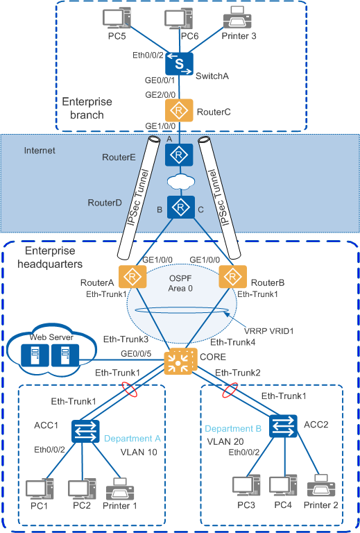
Solution Overview
Deploy Huawei S2700&S3700 switches (ACC1, ACC2, and SwitchA) at the access layer, deploy Huawei S5700 switches (CORE) at the core layer, and deploy Huawei AR3200 routers (RouterA, RouterB, and RouterC) at the campus network egress.
In the headquarters, use redundancy between two AR egress routers (RouterA and RouterB) to ensure device-level reliability. In the branch, deploy one AR router as the egress router.
In the headquarters, set up a stack (CORE) between two S5700 core switches to ensure device-level reliability.
In the headquarters, deploy Eth-Trunks between access switches, the CORE, and egress routers to ensure link-level reliability.
In the headquarters, assign a VLAN to each department and transmit services between departments at Layer 3 through VLANIF interfaces of the CORE.
Use the CORE of the headquarters as the gateway for users and servers, and deploy a DHCP server to assign IP addresses to users.
Deploy the gateway for branch users on the egress router.
Deploy VRRP between the two egress routers of the headquarters to ensure reliability.
Construct an Internet Protocol Security (IPSec) VPN between the headquarters and branch over the Internet to enable communication while ensuring data transmission security.
Deploy Open Shortest Path First (OSPF) between the two egress routers and CORE of the headquarters to advertise user routes for future capacity expansion and maintenance.
Configuration Roadmap
The configuration roadmap is as follows:
Deploy the headquarters and branch campus networks.
In the headquarters, deploy a stack and link aggregation, configure VLANs and IP addresses for interfaces, and deploy a DHCP server to allow users in the headquarters campus network to communicate. Users within a department communicate at Layer 2 through access switches, and users in different departments communicate at Layer 3 through the VLANIF interfaces of the CORE.
In the branch, configure VLANs and IP addresses for interfaces on access switches and egress routers, and deploy a DHCP server to allow users in the branch campus network to communicate.
Deploy VRRP.
To ensure reliability between the CORE and two egress routers of the headquarters, deploy VRRP between the two egress routers so that VRRP heartbeat packets are exchanged through the CORE. Configure RouterA as the master device and RouterB as the backup device.
To prevent service interruption in the case of an uplink failure on RouterA, associate the VRRP status with the uplink interface of RouterA. The association ensures a fast VRRP switchover when the uplink fails.
Deploy routes.
To steer uplink traffic of devices, configure a default route with the VRRP virtual address as the next hop on the CORE of the headquarters, and configure a default route on each egress router of the headquarters and branch, with the next hop pointing to the IP address of the connected carrier network device (public network gateway address).
To steer the return traffic of two egress routers of the headquarters, configure OSPF between the two egress routers and CORE, and advertise all user network segments on the CORE into OSPF and then to the two egress routers.
On RouterD, to steer traffic generated by access to the web server from external networks, configure two static routes of which the destination address is the public network address of the web server and next-hop addresses are uplink interface addresses of the two egress routers. To ensure simultaneous route switchover and VRRP switchover, set the route with next hop pointing to RouterA as the preferred one. When this route fails, the route with next hop pointing to RouterB takes effect.
Configure NAT outbound.
To enable internal users to access the Internet, configure NAT on the uplink interfaces of the two egress routers for translation between private network addresses and public network addresses. Use an ACL to permit the source IP address of packets from Department A so that users in Department A can access the Internet while users in Department B cannot.
Configure a NAT server.
To enable external users to access the internal web server, configure a NAT server on the uplink interfaces of the two egress routers to translate between the public and private network addresses of the server.
Deploy IPSec VPN.
To enable users in the headquarters and branch to communicate through a VPN, configure IPSec VPN between the egress routers of the headquarters and branch for secure communication.

For the enterprise internal network configuration, see "Small- and Mid-Sized Campus Networks" in the HUAWEI S Series Campus Switches Quick Configuration.
Data Plan
Table 1, Table 2, and Table 3 provide the data plan.
Device |
LAG Interface |
Physical Interface |
|---|---|---|
RouterA |
Eth-Trunk1 |
GE2/0/0 GE2/0/1 |
RouterB |
Eth-Trunk1 |
GE2/0/0 GE2/0/1 |
CORE |
Eth-Trunk1 |
GE0/0/1 GE1/0/1 |
Eth-Trunk2 |
GE0/0/2 GE1/0/2 |
|
Eth-Trunk3 |
GE0/0/3 GE1/0/3 |
|
Eth-Trunk4 |
GE0/0/4 GE1/0/4 |
|
ACC1 |
Eth-Trunk1 |
GE0/0/1 GE0/0/2 |
ACC2 |
Eth-Trunk1 |
GE0/0/1 GE0/0/2 |
All Eth-Trunk interfaces work in Link Aggregation Control Protocol (LACP) mode.
Device |
Data |
Remarks |
|---|---|---|
RouterA |
Eth-Trunk1.100: Configure a dot1q termination sub-interface to terminate packets of VLAN 100. |
Connects to the CORE of the headquarters. |
RouterB |
Eth-Trunk1.100: Configure a dot1q termination sub-interface to terminate packets of VLAN 100. |
Connects to the CORE of the headquarters. |
CORE |
Eth-Trunk1: a trunk interface that transparently transmits packets of VLAN 10. |
Connects to department A of the headquarters. |
Eth-Trunk2: a trunk interface that transparently transmits packets of VLAN 20. |
Connects to department B of the headquarters. |
|
GE0/0/5: an access interface with VLAN 30 as the default VLAN. |
Connects to the web server of the headquarters. |
|
Eth-Trunk3: a trunk interface that transparently transmits packets of VLAN 100. |
Connects to RouterA of the headquarters. |
|
Eth-Trunk4: a trunk interface that transparently transmits packets of VLAN 100. |
Connects to RouterB of the headquarters. |
|
ACC1 |
Eth-Trunk1: a trunk interface that transparently transmits packets of VLAN 10. |
Connects to the CORE of the headquarters. |
Ethernet0/0/2: an access interface with VLAN 10 as the default VLAN. |
Connects to PC1 in department A. |
|
ACC2 |
Eth-Trunk1: a trunk interface that transparently transmits packets of VLAN 20. |
Connects to the CORE of the headquarters. |
Ethernet0/0/2: an access interface with VLAN 20 as the default VLAN. |
Connects to PC3 in department B. |
|
RouterC |
GE2/0/0.200: Configure a dot1q termination sub-interface to terminate packets of VLAN 200. |
Connects to SwitchA (access switch) of the branch. |
SwitchA |
GE0/0/1: a trunk interface that transparently transmits packets of VLAN 200. |
Connects to RouterC (egress router) of the branch. |
Ethernet0/0/2: an access interface with VLAN 200 as the default VLAN. |
Connects to PC5 in the branch. |
Device |
Data |
Remarks |
|---|---|---|
RouterA |
GE1/0/0: 202.10.1.2/24 Eth-Trunk1.100: 10.10.100.2/24 |
GE1/0/0 connects to the carrier network. Eth-Trunk1.100 connects to the CORE of the headquarters. |
RouterB |
GE1/0/0: 202.10.2.2/24 Eth-Trunk1.100: 10.10.100.3/24 |
- |
CORE |
VLANIF 10: 10.10.10.1/24 VLANIF 20: 10.10.20.1/24 VLANIF 30: 10.10.30.1/24 VLANIF 100: 10.10.100.4/24 |
VLANIF 10 functions as the user gateway of department A. VLANIF 20 functions as the user gateway of department B. VLANIF 30 functions as the gateway of the web server. VLANIF 100 connects to egress routers. |
Web server |
IP address: 10.10.30.2/24 Default gateway: 10.10.30.1 |
Public network IP address translated by the NAT server: 202.10.100.3 |
PC1 |
IP address: 10.10.10.2/24 Default gateway: 10.10.10.1 |
IP address 10.10.10.2/24 is allocated to the PC through DHCP in this example. |
PC3 |
IP address: 10.10.20.2/24 Default gateway: 10.10.20.1 |
IP address 10.10.20.2/24 is allocated to the PC through DHCP in this example. |
RouterD |
InterfaceB: interface number GigabitEthernet1/0/0 and IP address 202.10.1.1/24 InterfaceC: interface number GigabitEthernet2/0/0 and IP address 202.10.2.1/24 |
RouterD is a carrier network device. The interface number used here is an example. When configuring a device, use the actual interface number. |
RouterE |
InterfaceA: interface number GigabitEthernet1/0/0 and IP address 203.10.1.1/24 |
RouterE is a carrier network device. The interface number used here is an example. When configuring a device, use the actual interface number. |
RouterC |
GE1/0/0: 203.10.1.2/24 GE2/0/0.200: 10.10.200.1/24 |
- |
PC5 |
IP address: 10.10.200.2/24 Default gateway: 10.10.200.1 |
IP address 10.10.200.2/24 is allocated to the PC through DHCP in this example. |
Procedure
- Configure Eth-Trunks between the CORE and two egress routers of the headquarters.
# Configure the CORE.
<HUAWEI> system-view
[HUAWEI] sysname CORE
[CORE] interface eth-trunk 3
[CORE-Eth-Trunk3] mode lacp
[CORE-Eth-Trunk3] quit
[CORE] interface eth-trunk 4
[CORE-Eth-Trunk4] mode lacp
[CORE-Eth-Trunk4] quit
[CORE] interface gigabitethernet 0/0/3
[CORE-GigabitEthernet0/0/3] eth-trunk 3
[CORE-GigabitEthernet0/0/3] quit
[CORE] interface gigabitethernet 1/0/3
[CORE-GigabitEthernet1/0/3] eth-trunk 3
[CORE-GigabitEthernet1/0/3] quit
[CORE] interface gigabitethernet 0/0/4
[CORE-GigabitEthernet0/0/4] eth-trunk 4
[CORE-GigabitEthernet0/0/4] quit
[CORE] interface gigabitethernet 1/0/4
[CORE-GigabitEthernet1/0/4] eth-trunk 4
[CORE-GigabitEthernet1/0/4] quit
# Configure RouterA (egress router) of the headquarters. The configuration of RouterB is similar to that of RouterA.
<Huawei> system-view
[Huawei] sysname RouterA
[RouterA] interface eth-trunk 1
[RouterA-Eth-Trunk1] undo portswitch
[RouterA-Eth-Trunk1] mode lacp-static
[RouterA-Eth-Trunk1] quit
[RouterA] interface gigabitethernet 2/0/0
[RouterA-GigabitEthernet2/0/0] eth-trunk 1
[RouterA-GigabitEthernet2/0/0] quit
[RouterA] interface gigabitethernet 2/0/1
[RouterA-GigabitEthernet2/0/1] eth-trunk 1
[RouterA-GigabitEthernet2/0/1] quit
- Configure VLANs and IP addresses for interfaces.
# Configure the CORE.
[CORE] vlan 100
[CORE] quit
[CORE] interface Eth-Trunk 3
[CORE-Eth-Trunk3] port link-type trunk
[CORE-Eth-Trunk3] port trunk allow-pass vlan 100
[CORE-Eth-Trunk3] quit
[CORE] interface Eth-Trunk 4
[CORE-Eth-Trunk4] port link-type trunk
[CORE-Eth-Trunk4] port trunk allow-pass vlan 100
[CORE-Eth-Trunk4] quit
[CORE] interface vlanif 100
[CORE-Vlanif100] ip address 10.10.100.4 24
[CORE-Vlanif100] quit
# Configure RouterA (egress router) of the headquarters. The configuration of RouterB is similar to that of RouterA.
[RouterA] interface Eth-Trunk 1.100
[RouterA-Eth-Trunk1.100] ip address 10.10.100.2 24
[RouterA-Eth-Trunk1.100] dot1q termination vid 100
[RouterA-Eth-Trunk1.100] arp broadcast enable     //Enable the interface to process ARP broadcast packets. This function has been enabled on AR3200 series routers running V200R003C01 and later versions by default.
[RouterA-Eth-Trunk1.100] quit
[RouterA] interface gigabitethernet 1/0/0
[RouterA-GigabitEthernet1/0/0] ip address 202.10.1.2 24
[RouterA-GigabitEthernet1/0/0] quit
# Configure RouterC (egress router) of the branch.
<Huawei> system-view
[Huawei] sysname RouterC
[RouterC] interface gigabitethernet 1/0/0
[RouterC-GigabitEthernet1/0/0] ip address 203.10.1.2 24
[RouterC-GigabitEthernet1/0/0] quit
- Deploy VRRP. Configure VRRP between RouterA and RouterB of the headquarters, and configure RouterA as the master device and RouterB as the backup device.
# Configure RouterA.
[RouterA] interface Eth-Trunk 1.100
[RouterA-Eth-Trunk1.100] vrrp vrid 1 virtual-ip 10.10.100.1
[RouterA-Eth-Trunk1.100] vrrp vrid 1 priority 120
[RouterA-Eth-Trunk1.100] vrrp vrid 1 track interface GigabitEthernet1/0/0 reduced 40
[RouterA-Eth-Trunk1.100] quit
 //To prevent service interruption in the case of an uplink failure on RouterA, associate the VRRP status with the uplink interface of RouterA. The association ensures a fast VRRP switchover when the uplink fails.
# Configure RouterB.
[RouterB] interface Eth-Trunk 1.100
[RouterB-Eth-Trunk1.100] vrrp vrid 1 virtual-ip 10.10.100.1
[RouterB-Eth-Trunk1.100] quit
After the configuration is complete, a VRRP group should have been set up between RouterA and RouterB. You can run the display vrrp command to view the VRRP status of the two egress routers.
# Check that the VRRP status of RouterA is Master.
[RouterA] display vrrp
  Eth-Trunk1.100 | Virtual Router 1
    State : Master
    Virtual IP : 10.10.100.1
    Master IP : 10.10.100.2
    PriorityRun : 120
    PriorityConfig : 120
    MasterPriority : 120
    Preempt : YES   Delay Time : 0 s
    TimerRun : 1 s
    TimerConfig : 1 s
    Auth type : NONE
    Virtual MAC : 0000-5e00-0101
    Check TTL : YES
    Config type : normal-vrrp
    Backup-forward : disabled
    Track IF : GigabitEthernet1/0/0   Priority reduced : 40
    IF state : UP
    Create time : 2015-05-18 06:53:47 UTC-05:13
    Last change time : 2015-05-18 06:54:14 UTC-05:13
# Check that the VRRP status of RouterB is Backup.
[RouterB] display vrrp Eth-Trunk1.100 | Virtual Router 1 State : Backup Virtual IP : 10.10.100.1 Master IP : 10.10.100.2 PriorityRun : 100 PriorityConfig : 100 MasterPriority : 120 Preempt : YES Delay Time : 0 s TimerRun : 1 s TimerConfig : 1 s Auth type : NONE Virtual MAC : 0000-5e00-0101 Check TTL : YES Config type : normal-vrrp Backup-forward : disabled Create time : 2015-05-18 06:53:52 UTC-05:13 Last change time : 2015-05-18 06:57:12 UTC-05:13 - Deploy routes.
- Configure NAT outbound.
- Deploy a NAT server.
The headquarters has a web server. You need to configure a NAT server on the two egress routers (RouterA and RouterB) to allow external users to access the internal web server.
# Configure RouterA.
[RouterA] interface GigabitEthernet1/0/0
[RouterA-GigabitEthernet1/0/0] nat server protocol tcp global 202.10.100.3 www inside 10.10.30.2 8080
[RouterA-GigabitEthernet1/0/0] quit
# Configure RouterB.
[RouterB] interface GigabitEthernet1/0/0
[RouterB-GigabitEthernet1/0/0] nat server protocol tcp global 202.10.100.3 www inside 10.10.30.2 8080
[RouterB-GigabitEthernet1/0/0] quit
# After the configuration is complete, run the display nat server command to view NAT server configuration. The following uses the display on RouterA as an example.
[RouterA] display nat server Nat Server Information: Interface : GigabitEthernet1/0/0 Global IP/Port : 202.10.100.3/80(www) Inside IP/Port : 10.10.30.2/8080 Protocol : 6(tcp) VPN instance-name : ---- Acl number : ---- Description : ---- Total : 1 - Deploy IPSec VPN so that the headquarters and branch can communicate through the VPN over the Internet and data communication can be protected.
- Verify the configuration.
# Run the ping command to test the connectivity between the headquarters and branch.
PC1>ping 10.10.200.2

Ping 10.10.200.2: 32 data bytes, Press Ctrl_C to break
From 10.10.200.2: bytes=32 seq=1 ttl=126 time=140 ms
From 10.10.200.2: bytes=32 seq=2 ttl=126 time=235 ms
From 10.10.200.2: bytes=32 seq=3 ttl=126 time=266 ms
From 10.10.200.2: bytes=32 seq=4 ttl=126 time=140 ms
From 10.10.200.2: bytes=32 seq=5 ttl=126 time=141 ms

--- 10.10.200.2 ping statistics ---
  5 packet(s) transmitted
  5 packet(s) received
  0.00% packet loss
  round-trip min/avg/max = 140/184/266 ms
PC3>ping 10.10.200.2

Ping 10.10.200.2: 32 data bytes, Press Ctrl_C to break
From 10.10.200.2: bytes=32 seq=1 ttl=126 time=156 ms
From 10.10.200.2: bytes=32 seq=2 ttl=126 time=297 ms
From 10.10.200.2: bytes=32 seq=3 ttl=126 time=156 ms
From 10.10.200.2: bytes=32 seq=4 ttl=126 time=141 ms
From 10.10.200.2: bytes=32 seq=5 ttl=126 time=109 ms

--- 10.10.200.2 ping statistics ---
  5 packet(s) transmitted
  5 packet(s) received
  0.00% packet loss
  round-trip min/avg/max = 109/171/297 ms
The preceding command output shows that PC1 and PC5, and PC3 and PC5 can communicate with each other, and the headquarters and branch can communicate through the VPN over the Internet.
# Verify the connectivity between departments of the headquarters and the Internet. In the following example, ping the public network gateway 202.10.1.1 of the headquarters from PC1 and PC3.
PC1>ping 202.10.1.1

Ping 202.10.1.1: 32 data bytes, Press Ctrl_C to break
From 202.10.1.1: bytes=32 seq=1 ttl=253 time=235 ms
From 202.10.1.1: bytes=32 seq=2 ttl=253 time=109 ms
From 202.10.1.1: bytes=32 seq=3 ttl=253 time=79 ms
From 202.10.1.1: bytes=32 seq=4 ttl=253 time=63 ms
From 202.10.1.1: bytes=32 seq=5 ttl=253 time=63 ms

--- 202.10.1.1 ping statistics ---
  5 packet(s) transmitted
  5 packet(s) received
  0.00% packet loss
  round-trip min/avg/max = 63/109/235 ms
PC3>ping 202.10.1.1

Ping 202.10.1.1: 32 data bytes, Press Ctrl_C to break
Request timeout!
Request timeout!
Request timeout!
Request timeout!
Request timeout!

--- 202.10.1.1 ping statistics ---
  5 packet(s) transmitted
  0 packet(s) received
  100.00% packet loss
The preceding command output shows that users (such as PC1) in Department A can access the public network but users (such as PC3) in Department B cannot.
Configuration Files
Core switch configuration file
#
sysname CORE
#
vlan batch 100
#
interface Vlanif100
 ip address 10.10.100.4 255.255.255.0
#
interface Eth-Trunk3
 port link-type trunk
 port trunk allow-pass vlan 100
 mode lacp

#
interface Eth-Trunk4
 port link-type trunk
 port trunk allow-pass vlan 100
 mode lacp

#
interface GigabitEthernet0/0/3
 eth-trunk 3
#
interface GigabitEthernet0/0/4
 eth-trunk 4
#
interface GigabitEthernet1/0/3
 eth-trunk 3
#
interface GigabitEthernet1/0/4
 eth-trunk 4
#
ospf 1 router-id 10.3.3.3
 area 0.0.0.0
  network 10.10.100.0 0.0.0.255
  network 10.10.10.0 0.0.0.255
  network 10.10.20.0 0.0.0.255
  network 10.10.30.0 0.0.0.255
#
ip route-static 0.0.0.0 0.0.0.0 10.10.100.1
#
return
RouterA configuration file
#
 sysname RouterA
#
acl number 3000
 rule 5 deny ip source 10.10.10.0 0.0.0.255 destination 10.10.200.0 0.0.0.255
 rule 10 deny ip source 10.10.20.0 0.0.0.255 destination 10.10.200.0 0.0.0.255
 rule 15 permit ip source 10.10.10.0 0.0.0.255
acl number 3001
 rule 5 permit ip source 10.10.10.0 0.0.0.255 destination 10.10.200.0 0.0.0.255
 rule 10 permit ip source 10.10.20.0 0.0.0.255 destination 10.10.200.0 0.0.0.255
#
ipsec proposal tran1
 esp authentication-algorithm sha2-256
 esp encryption-algorithm aes 128
#
ike proposal 5
 encryption-algorithm aes-cbc-128
#
ike peer vpn v1
 pre-shared-key cipher "@J*U2S*(7F,YWX*NZ55OA!!
 ike-proposal 5
 dpd type periodic
 dpd idle-time 10
 remote-address 203.10.1.2
#
ipsec policy ipsec_vpn 10 isakmp
 security acl 3001
 ike-peer vpn
 proposal tran1
#
interface Eth-Trunk1
 undo portswitch
 mode lacp-static
#
interface Eth-Trunk1.100
 dot1q termination vid 100
 ip address 10.10.100.2 255.255.255.0
 vrrp vrid 1 virtual-ip 10.10.100.1
 vrrp vrid 1 priority 120
 vrrp vrid 1 track interface GigabitEthernet1/0/0 reduced 40
 arp broadcast enable
#
interface GigabitEthernet1/0/0
 ip address 202.10.1.2 255.255.255.0
 ipsec policy ipsec_vpn
 nat server protocol tcp global 202.10.100.3 www inside 10.10.30.2 8080
 nat outbound 3000
#
interface GigabitEthernet2/0/0
 eth-trunk 1
#
interface GigabitEthernet2/0/1
 eth-trunk 1
#
ospf 1 router-id 10.1.1.1
 area 0.0.0.0
  network 10.10.100.0 0.0.0.255
#
ip route-static 0.0.0.0 0.0.0.0 202.10.1.1
#
return
RouterB configuration file
#
 sysname RouterB
#
acl number 3000
 rule 5 deny ip source 10.10.10.0 0.0.0.255 destination 10.10.200.0 0.0.0.255
 rule 10 deny ip source 10.10.20.0 0.0.0.255 destination 10.10.200.0 0.0.0.255
 rule 15 permit ip source 10.10.10.0 0.0.0.255
acl number 3001
 rule 5 permit ip source 10.10.10.0 0.0.0.255 destination 10.10.200.0 0.0.0.255
 rule 10 permit ip source 10.10.20.0 0.0.0.255 destination 10.10.200.0 0.0.0.255
#
ipsec proposal tran1
 esp authentication-algorithm sha2-256
 esp encryption-algorithm aes 128
#
ike proposal 5
 encryption-algorithm aes-cbc-128
#
ike peer vpn v1
 pre-shared-key cipher "@J*U2S*(7F,YWX*NZ55OA!!
 ike-proposal 5
 dpd type periodic
 dpd idle-time 10
 remote-address 203.10.1.2
#
ipsec policy ipsec_vpn 10 isakmp
 security acl 3001
 ike-peer vpn
 proposal tran1
#
interface Eth-Trunk1
 undo portswitch
 mode lacp-static
#
interface Eth-Trunk1.100
 dot1q termination vid 100
 ip address 10.10.100.3 255.255.255.0
 vrrp vrid 1 virtual-ip 10.10.100.1
 arp broadcast enable
#
interface GigabitEthernet1/0/0
 ip address 202.10.2.2 255.255.255.0
 ipsec policy ipsec_vpn
 nat server protocol tcp global 202.10.100.3 www inside 10.10.30.2 8080
 nat outbound 3000
#
interface GigabitEthernet2/0/0
 eth-trunk 1
#
interface GigabitEthernet2/0/1
 eth-trunk 1
#
ospf 1 router-id 10.2.2.2
 area 0.0.0.0
  network 10.10.100.0 0.0.0.255
#
ip route-static 0.0.0.0 0.0.0.0 202.10.2.1
#
return
Configuration file of the branch egress router RouterC
#
 sysname RouterC
#
acl number 3000
 rule 5 deny ip source 10.10.200.0 0.0.0.255 destination 10.10.10.0 0.0.0.255
 rule 10 deny ip source 10.10.200.0 0.0.0.255 destination 10.10.20.0 0.0.0.255
 rule 15 permit ip source 10.10.200.0 0.0.0.255
acl number 3001
 rule 5 permit ip source 10.10.200.0 0.0.0.255 destination 10.10.10.0 0.0.0.255
 rule 10 permit ip source 10.10.200.0 0.0.0.255 destination 10.10.20.0 0.0.0.255
#
ipsec proposal tran1
 esp authentication-algorithm sha2-256
 esp encryption-algorithm aes 128
#
ike proposal 5
 encryption-algorithm aes-cbc-128
#
ike peer vpnr1 v1
 pre-shared-key cipher "@J*U2S*(7F,YWX*NZ55OA!!
 ike-proposal 5
 dpd type periodic
 dpd idle-time 10
 remote-address 202.10.1.2
#
ike peer vpnr2 v1
 pre-shared-key cipher "@J*U2S*(7F,YWX*NZ55OA!!
 ike-proposal 5
 dpd type periodic
 dpd idle-time 10
 remote-address 202.10.2.2
#
ipsec policy ipsec_vpn 10 isakmp
 security acl 3001
 ike-peer vpnr1
 proposal tran1
#
ipsec policy ipsec_vpn 20 isakmp
 security acl 3001
 ike-peer vpnr2
 proposal tran1
#
interface GigabitEthernet1/0/0
 ip address 203.10.1.2 255.255.255.0
 ipsec policy ipsec_vpn
 nat outbound 3000
#
ip route-static 0.0.0.0 0.0.0.0 203.10.1.1
#
return
Configuration file of the headquarters carrier router RouterD
#
 sysname RouterD
#
interface GigabitEthernet1/0/0
 ip address 202.10.1.1 255.255.255.0
#
interface GigabitEthernet2/0/0
 ip address 202.10.2.1 255.255.255.0
#
ip route-static 202.10.100.0 255.255.255.0 202.10.1.2 preference 40
ip route-static 202.10.100.0 255.255.255.0 202.10.2.2
#
return
Configuration file of the branch carrier router RouterE
#
 sysname RouterE
#
interface GigabitEthernet1/0/0
 ip address 203.10.1.1 255.255.255.0
#
return