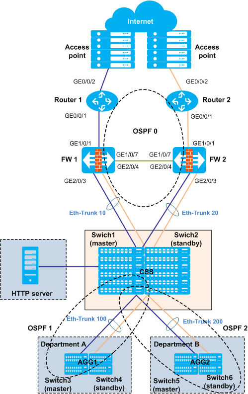
Example for Configuring the Egress of a Large-Sized Campus (Firewalls Are Connected to Core Switches in In-line Mode)
Networking Requirements
- Users on the internal network use private IP addresses and user IP addresses are allocated using DHCP.
- Users in department A can access the Internet, and users in department B cannot access the Internet.
- Users on internal and external networks can access the HTTP server.
- Each node uses the redundancy design to ensure network reliability.
Device Selection
This example applies to the following products and versions. If other products or versions are used, the configurations may vary. For details, see a related configuration manual.
Device Type |
Device Model |
Device Version |
|---|---|---|
Access router |
AR3600 series routers |
V200R007C00 |
Firewall |
USG9500 series firewalls |
V500R001C20 |
Core switches |
S12700 series switches |
V200R008C00 |
Aggregation switch |
S5720-EI series switches |
V200R008C00 |
Deployment Overview
- Routing deployment
- Configure a loopback interface address as the router ID on each device.
- Add egress routers, firewalls, and core switches to OSPF area 0. Configure egress routers as Autonomous System Border Routers (ASBRs) and core switches as Area Border Routers (ABRs).
- Configure Open Shortest Path First (OSPF) areas 1 and 2 for departments A and B, respectively, and configure the two OSPF areas as Not-So-Stubby Areas (NSSAs) to reduce the number of LSAs transmitted between OSPF areas.
- To guide uplink traffic on each device, configure a default route pointing to the firewall on the core switch, configure a default route pointing to the egress router on the firewall, and configure a default route pointing to the address of the interconnected interface (public gateway address) of the carrier's device.
Reliability deployment
You are advised to use CSS+iStack+Eth-Trunk to build a loop-free Ethernet.
- Deploy cluster switch system (CSS) on core switches and intelligent Stack (iStack) on aggregation switches to ensure device-level reliability.
- To improve link reliability, use Eth-Trunks between core switches and firewalls, between core switches and aggregation switches, and between aggregation switches and access switches.
- Deploy the Huawei Redundancy Protocol (HRP) on firewalls to implement load balancing.
- Dynamic Host Configuration Protocol (DHCP) deployment
- Configure the core switch as the DHCP server to allocate IP addresses to users.
- Configure the DHCP relay function on the aggregation switch to ensure that the DHCP server can allocate IP addresses to users.
- Network Address Translation (NAT) deployment
- To ensure that users on the internal network can access the Internet, configure NAT on uplink interfaces of the two egress routers to translate private addresses into public addresses. Configure an access control list (ACL) to match the source IP address of department A so that users of department A can access the Internet and users of department B cannot access the Internet.
- To ensure that users on the external network can access the HTTP server, configure the NAT server on two egress routers.
Security deployment
Configure security policies on firewalls to filter traffic and ensure network security.
Data Plan
Device |
Interface Number |
Member Interface |
VLANIF Interface |
IP Address |
Remote Device |
Remote Interface Number |
|
|---|---|---|---|---|---|---|---|
Router1 |
GE0/0/1 |
- |
- |
10.1.1.1/24 |
FW1 |
GE1/0/1 |
|
GE0/0/2 |
- |
- |
202.10.1.1/24 |
Assume that the interface connected to an interface of a carrier's device and the IP address is a public one allocated by the carrier. |
|||
Router2 |
GE0/0/1 |
- |
- |
10.2.1.1/24 |
FW2 |
GE1/0/1 |
|
GE0/0/2 |
- |
- |
202.10.2.1/24 |
Assume that the interface connected to an interface of a carrier's device and the IP address is a public one allocated by the carrier. |
|||
FW1 |
GE1/0/1 |
- |
- |
10.1.1.2/24 |
Router1 |
GE0/0/1 |
|
GE1/0/7 |
- |
- |
10.10.1.1/24 |
FW2 |
GE1/0/7 |
||
Eth-Trunk10 |
GE2/0/3 |
- |
10.3.1.1/24 |
CSS |
Eth-Trunk 10 |
||
GE2/0/4 |
|||||||
FW2 |
GE1/0/1 |
- |
- |
10.2.1.2/24 |
Router2 |
GE0/0/1 |
|
GE1/0/7 |
- |
- |
10.10.1.2/24 |
FW1 |
GE1/0/7 |
||
Eth-Trunk 20 |
GE2/0/3 |
- |
10.4.1.1/24 |
CSS |
Eth-Trunk 20 |
||
GE2/0/4 |
|||||||
CSS |
GE1/1/0/10 |
- |
VLANIF 300 |
10.100.1.1 |
HTTP server |
Ethernet interface |
|
Eth-Trunk 10 |
GE1/1/0/3 |
- |
10.3.1.2/24 |
FW1 |
Eth-Trunk 10 |
||
GE2/1/0/3 |
|||||||
Eth-Trunk 20 |
GE1/1/0/4 |
- |
10.4.1.2/24 |
FW2 |
Eth-Trunk 20 |
||
GE2/1/0/4 |
|||||||
Eth-Trunk 100 |
GE1/2/0/3 |
VLANIF 100 |
10.5.1.1/24 |
AGG1 |
Eth-Trunk 100 |
||
GE2/2/0/3 |
|||||||
Eth-Trunk 200 |
GE1/2/0/4 |
VLANIF 200 |
10.6.1.1/24 |
AGG2 |
Eth-Trunk 200 |
||
GE2/2/0/4 |
|||||||
AGG1 |
Eth-Trunk 100 |
GE1/0/1 |
VLANIF 100 |
10.5.1.2/24 |
CSS |
Eth-Trunk 100 |
|
GE2/0/1 |
|||||||
Eth-Trunk 500 |
GE1/0/5 |
VLANIF 500 |
192.168.1.1/24 |
Assume that the interface is used to connect to department A and its IP address is the gateway address of department A. |
|||
GE2/0/5 |
|||||||
AGG2 |
Eth-Trunk 200 |
GE1/0/1 |
VLANIF 200 |
10.6.1.2/24 |
CSS |
||
GE2/0/1 |
|||||||
Eth-Trunk 600 |
GE1/0/5 |
VLANIF600 |
192.168.2.1/24 |
Assume that the interface is used to connect to department B and its IP address is the gateway address of department B. |
|||
GE2/0/5 |
|||||||
HTTP server |
Ethernet interface |
- |
- |
10.100.1.10/24 |
CSS |
GE1/1/0/10 |
|
Configuration Roadmap
Step |
Configuration Roadmap |
Involved Product |
|---|---|---|
1 |
(1) Configure CSS on core switches. (2) Configure iStack on aggregation switches. |
Core switches (Switch1 and Switch2) and aggregation switches (Switch3, Switch4, Switch5, and Switch6) |
2 |
Configure Eth-Trunks to improve the link reliability. (1) Configure Eth-Trunks between core switches (CSS) and firewalls. (2) Configure Eth-Trunks between core switches (CSS) and aggregation switches (AGG). (3) Configure Eth-Trunks between aggregation switches and access switches. |
Core switches (CSS), firewalls (FW1 and FW2), and aggregation switches (AGG1 and AGG2) |
3 |
Assign an IP address to each interface. (1) Configure IP addresses for uplink and downlink interfaces of routers. (2) Configure IP addresses for uplink and downlink interfaces of firewalls. (3) Configure IP addresses for uplink and downlink interfaces of core switches. (4) Configure IP addresses for uplink and downlink interfaces of aggregation switches. |
Routers (Router1 and Router2), firewalls (FW1 and FW2), core switches (CSS), and aggregation switches (AGG1 and AGG2) |
4 |
Configure a routing protocol. Configure OSPF on the internal network. (1) Configure OSPF area 0 on uplink interfaces of routers, firewalls, and core switches. (2) Configure OSPF areas 1 and 2 on core and aggregation switches, configure the two OSPF areas as NSSAs, and add downlink interfaces of core switches to NSSAs. (3) Configure a default route pointing to the firewall on the core switch, configure a default route pointing to the egress router on the firewall, and configure a default route pointing to the address of the interconnected interface (public gateway address) of the carrier's device. |
Routers (Router1 and Router2), firewalls (FW1 and FW2), and core switches (CSS) |
5 |
Configure zones that interfaces belong to. (1) Add the interface connected to the external network to the untrusted zone. (2) Add the interface connected to the internal network to the trusted zone. (3) Add the heartbeat interface enabled with HRP to the DMZ. |
Firewalls (FW1 and FW2) |
6 |
Configure HRP. (1) Associate VRRP Group Management Protocol (VGMP) groups with uplink and downlink interfaces. (2) Specify heartbeat interfaces and enable HRP. (3) Enable quick session backup to implement load balancing between two firewalls. |
Firewalls (FW1 and FW2) |
7 |
Configure DHCP. (1) Configure the DHCP server on core switches and specify the address pool and gateway address. (2) Configure the DHCP relay function on aggregation switches. |
Core switches (CSS) and aggregation switches (AGG1 and AGG2) |
8 |
Configure NAT. (1) Configure NAT on two egress routers so that users of department A can access the Internet and users of department B cannot access the Internet. (2) Configure the NAT server on two egress routers so that users on the external network can access the HTTP server. |
Egress routers (Router1 and Router2) |
9 |
Configure attack defense and enable defense against SYN Flood attacks and HTTP Flood attacks on firewalls to protect internal servers against attacks. |
Firewalls |
Procedure
- Configure CSS on core switches.
- Connect cables of CSS cards. CSS card EH1D2VS08000 is used as an example.Figure 2 CSS cabling
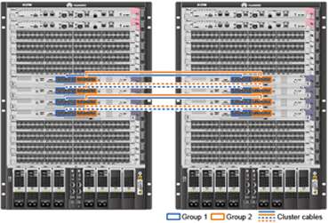

- One CSS card can only be connected to one CSS card in the other chassis but not the local chassis.
- An interface in group 1 of a CSS card can be connected to any interface in group 1 of the CSS card on the other chassis. The requirements for interfaces in group 2 are the same.
- CSS cards have the same number of cluster cables connected. (If the CSS cards have different numbers of cluster cables connected, the total cluster bandwidth is limited to the cluster with the least cluster cables connected.) In addition, interfaces on CSS cards are connected sequentially based on the interface number.
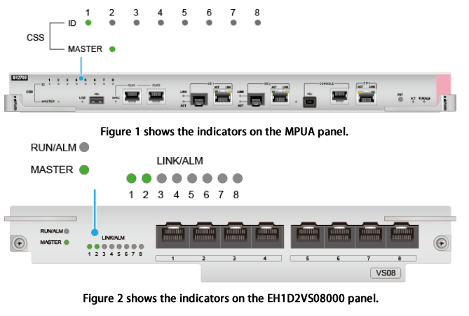
- Check the CSS status after the switches restart.
The MASTER indicator on the MPU is steady green, as shown in Figure 3.
- On Switch1, the CSS ID indicators numbered 1 on both MPUs are steady green. On Switch2, the CSS ID indicators numbered 2 on both MPUs are steady green.
- The LINK/ALM indicators of interfaces on all CSS cards connected to cluster cables are steady green.
- The MASTER indicators on all CSS cards in the active chassis are steady green, and the MASTER indicators on all CSS cards in the standby chassis are off.
After the CSS is established, subsequent operations will be performed on the master switch and data will be automatically synchronized to the standby switch. In a CSS, the physical interface number is in the format of interface type chassis ID/slot ID/interface card ID/interface sequence number, for example, 10GE1/1/0/9.
- Connect cables of CSS cards. CSS card EH1D2VS08000 is used as an example.
- Configure iStack on aggregation switches. S5720-EI series switches are used as an example. Service interface stacking is used.
Switch3 and Switch4 are used as an example. The configurations of Switch5 and Switch6 are similar, and are not mentioned here.
Connect cables after the iStack configuration is complete.
- Configure logical stack interfaces and add physical member interfaces to them.
Physical member interfaces of logical stack interface stack-port n/1 on one switch can only be connected to the interfaces of stack-port n/2 on a neighboring switch.
# Configure service interface GE0/0/28 on Switch3 as the physical member interface and add it to the corresponding logical stack interface.[Switch3] interface stack-port 0/1 [Switch3-stack-port0/1] port interface gigabitethernet 0/0/28 enable Warning: Enabling stack function may cause configuration loss on the interface, continue?[Y/N]:Y Info: This operation may take a few seconds. Please wait for a moment....... [Switch3-stack-port0/1] quit
# Configure service interface GE0/0/28 on Switch4 as the physical member interface and add it to the corresponding logical stack interface.[Switch4] interface stack-port 0/2 [Switch4-stack-port0/2] port interface gigabitethernet 0/0/28 enable Warning: Enabling stack function may cause configuration loss on the interface, continue?[Y/N]:Y Info: This operation may take a few seconds. Please wait for a moment....... [Switch4-stack-port0/2] quit
- Power off Switch3 and Switch4 and connect GE0/0/28 interfaces using the SFP+ stack cable.
Run the save command to save the configurations before you power off the switches.
Stack-port 0/1 of one switch must be connected to stack-port 0/2 of another switch. Otherwise, the stack cannot be set up.
Figure 4 Stack networking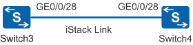
- Configure logical stack interfaces and add physical member interfaces to them.
- Configure inter-chassis Eth-Trunks between the CSS and firewalls and between the CSS and aggregation switches.
- Assign an IP address to each interface.# Configure Router1.
[Router1] interface loopback 0
[Router1-LoopBack0] ip address 1.1.1.1 32   //Configure the IP address as the router ID.
[Router1-LoopBack0] quit
[Router1] interface gigabitethernet 0/0/2
[Router1-GigabitEthernet0/0/2] ip address 202.10.1.1 24   //Configure an IP address for the interface connected to the external network.
[Router1-GigabitEthernet0/0/2] quit
[Router1] interface gigabitethernet 0/0/1
[Router1-GigabitEthernet0/0/1] ip address 10.1.1.1 24   //Configure an IP address for the interface connected to FW1.
[Router1-GigabitEthernet0/0/1] quit
# Configure Router2.[Router2] interface loopback 0 [Router2-LoopBack0] ip address 2.2.2.2 32 //Configure the IP address as the router ID. [Router2-LoopBack0] quit [Router2] interface gigabitethernet 0/0/2 [Router2-GigabitEthernet0/0/2] ip address 202.10.2.1 24 //Configure an IP address for the interface connected to the external network. [Router2-GigabitEthernet0/0/2] quit [Router2] interface gigabitethernet 0/0/1 [Router2-GigabitEthernet0/0/1] ip address 10.2.1.1 24 //Configure an IP address for the interface connected to FW2. [Router2-GigabitEthernet0/0/1] quit
# Configure FW1.[FW1] interface loopback 0 [FW1-LoopBack0] ip address 3.3.3.3 32 //Configure the IP address as the router ID. [FW1-LoopBack0] quit [FW1] interface gigabitethernet 1/0/1 [FW1-GigabitEthernet1/0/1] ip address 10.1.1.2 24 //Configure an IP address for the interface connected to Router1. [FW1-GigabitEthernet1/0/1] quit [FW1] interface gigabitethernet 1/0/7 [FW1-GigabitEthernet1/0/7] ip address 10.10.1.1 24 //Configure an IP address for the heartbeat interface enabled with HSB. [FW1-GigabitEthernet1/0/7] quit [FW1] interface eth-trunk 10 [FW1-Eth-Trunk10] ip address 10.3.1.1 24 //Configure an IP address for the Eth-Trunk connected to the CSS. [FW1-Eth-Trunk10] quit
# Configure FW2.[FW2] interface loopback 0 [FW2-LoopBack0] ip address 4.4.4.4 32 //Configure the IP address as the Router ID. [FW2-LoopBack0] quit [FW2] interface gigabitethernet 1/0/1 [FW2-GigabitEthernet1/0/1] ip address 10.2.1.2 24 //Configure an IP address for the interface connected to Router2. [FW2-GigabitEthernet1/0/1] quit [FW2] interface gigabitethernet 1/0/7 [FW2-GigabitEthernet1/0/7] ip address 10.10.1.2 24 //Configure an IP address for the heartbeat interface enabled with HSB. [FW2-GigabitEthernet1/0/7] quit [FW2] interface eth-trunk 20 [FW2-Eth-Trunk20] ip address 10.4.1.1 24 //Configure an IP address for the Eth-Trunk connected to the CSS. [FW2-Eth-Trunk20] quit
# Configure CSS.[CSS] interface loopback 0 [CSS-LoopBack0] ip address 5.5.5.5 32 //Configure the IP address as the Router ID. [CSS-LoopBack0] quit [CSS] interface eth-trunk 10 [CSS-Eth-Trunk10] undo portswitch //By default, an Eth-Trunk works in Layer 2 mode. To use an Eth-Trunk as a Layer 3 interface, run the undo portswitch command to switch the Eth-Trunk to Layer 3 mode. [CSS-Eth-Trunk10] ip address 10.3.1.2 24 //Configure an IP address for the Eth-Trunk connected to FW1. [CSS-Eth-Trunk10] quit [CSS] interface eth-trunk 20 [CSS-Eth-Trunk20] undo portswitch //By default, an Eth-Trunk works in Layer 2 mode. To use an Eth-Trunk as a Layer 3 interface, run the undo portswitch command to switch the Eth-Trunk to Layer 3 mode. [CSS-Eth-Trunk20] ip address 10.4.1.2 24 //Configure an IP address for the Eth-Trunk connected to FW2. [CSS-Eth-Trunk20] quit [CSS] vlan batch 100 200 300 //Create VLANs in a batch. [CSS] interface eth-trunk 100 [CSS-Eth-Trunk100] port link-type hybrid [CSS-Eth-Trunk100] port hybrid pvid vlan 100 [CSS-Eth-Trunk100] port hybrid untagged vlan 100 [CSS-Eth-Trunk100] quit [CSS] interface vlanif 100 [CSS-Vlanif100] ip address 10.5.1.1 24 //Configure an IP address for the interface connected to aggregation switch AGG1. [CSS-Vlanif100] quit [CSS] interface eth-trunk 200 [CSS-Eth-Trunk200] port link-type hybrid [CSS-Eth-Trunk200] port hybrid pvid vlan 200 [CSS-Eth-Trunk200] port hybrid untagged vlan 200 [CSS-Eth-Trunk200] quit [CSS] interface vlanif 200 [CSS-Vlanif200] ip address 10.6.1.1 24 //Configure an IP address for the interface connected to aggregation switch AGG2. [CSS-Vlanif200] quit [CSS] interface gigabitethernet 1/1/0/10 //Enter the view of the interface connected to the HTTP server. [CSS-GigabitEthernet1/1/0/10] port link-type access [CSS-GigabitEthernet1/1/0/10] port default vlan 300 //Add the access interface to VLAN 300. [CSS-GigabitEthernet1/1/0/10] quit [CSS] interface vlanif 300 [CSS-Vlanif300] ip address 10.100.1.1 24 //Configure an IP address for the interface connected to the HTTP server. [CSS-Vlanif300] quit
# Configure AGG1.[AGG1] interface loopback 0 [AGG1-LoopBack0] ip address 6.6.6.6 32 //Configure the IP address as the router ID. [AGG1-LoopBack0] quit [AGG1] vlan batch 100 500 [AGG1] interface eth-trunk 100 [AGG1-Eth-Trunk100] port link-type hybrid [AGG1-Eth-Trunk100] port hybrid pvid vlan 100 [AGG1-Eth-Trunk100] port hybrid untagged vlan 100 [AGG1-Eth-Trunk100] quit [AGG1] interface vlanif 100 [AGG1-Vlanif100] ip address 10.5.1.2 24 //Configure an IP address for the interface connected to the CSS. [AGG1-Vlanif100] quit [AGG1] interface eth-trunk 500 [AGG1-Eth-Trunk500] port link-type hybrid [AGG1-Eth-Trunk500] port hybrid pvid vlan 500 [AGG1-Eth-Trunk500] port hybrid untagged vlan 500 [AGG1-Eth-Trunk500] quit [AGG1] interface vlanif 500 [AGG1-Vlanif500] ip address 192.168.1.1 24 //Configure an IP address for the interface connected to the access switch and configure it as the gateway address of department A. [AGG1-Vlanif500] quit
# Configure AGG2.[AGG2] interface loopback 0 [AGG2-LoopBack0] ip address 7.7.7.7 32 //Configure the IP address as the router ID. [AGG2-LoopBack0] quit [AGG2] vlan batch 200 600 [AGG2] interface eth-trunk 200 [AGG2-Eth-Trunk200] port link-type hybrid [AGG2-Eth-Trunk200] port hybrid pvid vlan 200 [AGG2-Eth-Trunk200] port hybrid untagged vlan 200 [AGG2-Eth-Trunk200] quit [AGG2] interface vlanif 200 [AGG2-Vlanif200] ip address 10.6.1.2 24 //Configure an IP address for the interface connected to the CSS. [AGG2-Vlanif200] quit [AGG2] interface eth-trunk 600 [AGG2-Eth-Trunk600] port link-type hybrid [AGG2-Eth-Trunk600] port hybrid pvid vlan 600 [AGG2-Eth-Trunk600] port hybrid untagged vlan 600 [AGG2-Eth-Trunk600] quit [AGG2] interface vlanif 600 [AGG2-Vlanif600] ip address 192.168.2.1 24 //Configure an IP address for the interface connected to the access switch and configure it as the gateway address of department B. [AGG2-Vlanif600] quit
- On firewalls, configure security policies and zones that interfaces belong to.# Add interfaces to zones.
[FW1] firewall zone trust
[FW1-zone-trust] add interface Eth-Trunk 10   //Add Eth-Trunk 10 connected to the internal network to a trusted zone.
[FW1-zone-trust] quit
[FW1] firewall zone untrust
[FW1-zone-untrust] add interface gigabitethernet 1/0/1   //Add GE1/0/1 connected to the external network to an untrusted zone.
[FW1-zone-untrust] quit
[FW1] firewall zone dmz
[FW1-zone-dmz] add interface gigabitethernet 1/0/7   //Add GE1/0/7 to the DMZ.
[FW1-zone-dmz] quit
[FW2] firewall zone trust
[FW2-zone-trust] add interface Eth-Trunk 20   //Add Eth-Trunk 20 connected to the internal network to a trusted zone.
[FW2-zone-trust] quit
[FW2] firewall zone untrust
[FW2-zone-untrust] add interface gigabitethernet 1/0/1   //Add GE1/0/1 connected to the external network to an untrusted zone.
[FW2-zone-untrust] quit
[FW2] firewall zone dmz
[FW2-zone-dmz] add interface gigabitethernet 1/0/7   //Add GE1/0/7 to the DMZ.
[FW2-zone-dmz] quit
# Configure security policies on FW1.[FW1] policy interzone local untrust inbound [FW1-policy-interzone-local-untrust-inbound] policy 2 [FW1-policy-interzone-local-untrust-inbound-2] policy source 10.1.1.1 mask 24 //Configure a policy to permit the router in the untrusted zone to access the firewall. [FW1-policy-interzone-local-untrust-inbound-2] action permit [FW1-policy-interzone-local-untrust-inbound-2] quit [FW1-policy-interzone-local-untrust-inbound] quit [FW1] policy interzone local trust outbound [FW1-policy-interzone-local-trust-outbound] policy 1 [FW1-policy-interzone-local-trust-outbound-1] policy source 10.3.1.2 mask 24 //Configure a policy to permit the device in the trusted zone to access the firewall. [FW1-policy-interzone-local-trust-outbound-1] policy source 10.5.1.1 mask 24 // //Configure a policy to permit the device in the trusted zone to access the firewall. [FW1-policy-interzone-local-trust-outbound-1] policy source 192.168.1.1 mask 24 // //Configure a policy to permit the device in the trusted zone to access the firewall. [FW1-policy-interzone-local-outbound-inbound-1] action permit [FW1-policy-interzone-local-outbound-inbound-1] quit [FW1-policy-interzone-local-outbound-inbound] quit [FW1] policy interzone trust untrust outbound [FW1-policy-interzone-trust-untrust-outbound] policy 4 [FW1-policy-interzone-trust-untrust-outbound-4] policy source 192.168.1.1 mask 24 //Configure devices on network segment 192.168.1.0/24 to access the external network. [FW1-policy-interzone-trust-untrust-outbound-4] action permit [FW1-policy-interzone-trust-untrust-outbound-4] quit [FW1-policy-interzone-trust-untrust-outbound] quit [FW1] policy interzone trust untrust inbound [FW1-policy-interzone-trust-untrust-inbound] policy 3 [FW1-policy-interzone-trust-untrust-inbound-3] policy source 10.1.1.1 mask 24 //Configure the device at 10.1.1.1 to access the internal network. [FW1-policy-interzone-trust-untrust-inbound-3] action permit [FW1-policy-interzone-trust-untrust-inbound-3] quit [FW1-policy-interzone-trust-untrust-inbound] quit
# Configure security policies on FW2.[FW2] policy interzone local untrust inbound [FW2-policy-interzone-local-untrust-inbound] policy 2 [FW2-policy-interzone-local-untrust-inbound-2] policy source 10.2.1.1 mask 24 //Configure a policy to permit the router in the untrusted zone to access the firewall. [FW2-policy-interzone-local-untrust-inbound-2] action permit [FW2-policy-interzone-local-untrust-inbound-2] quit [FW2-policy-interzone-local-untrust-inbound] quit [FW2] policy interzone local trust outbound [FW2-policy-interzone-local-trust-outbound] policy 1 [FW2-policy-interzone-local-trust-outbound-1] policy source 10.4.1.2 mask 24 // //Configure a policy to permit the device in the trusted zone to access the firewall. [FW2-policy-interzone-local-trust-outbound-1] policy source 10.6.1.1 mask 24 // //Configure a policy to permit the device in the trusted zone to access the firewall. [FW2-policy-interzone-local-trust-outbound-1] policy source 192.168.2.1 mask 24 // //Configure a policy to permit the device in the trusted zone to access the firewall. [FW2-policy-interzone-local-dmz-inbound-1] action permit [FW2-policy-interzone-local-dmz-inbound-1] quit [FW2-policy-interzone-local-dmz-inbound] quit [FW2] policy interzone trust untrust inbound [FW2-policy-interzone-trust-untrust-inbound] policy 3 [FW2-policy-interzone-trust-untrust-inbound-3] policy source 10.2.1.1 mask 24 //Configure the device at 10.2.1.1 to access the internal network. [FW2-policy-interzone-trust-untrust-inbound-3] action permit [FW2-policy-interzone-trust-untrust-inbound-3] quit [FW2-policy-interzone-trust-untrust-inbound] quit
- Deploy routing.
- Configure DHCP in the CSS and AGG.# Configure the DHCP server in the CSS to allocate IP addresses to users.
[CSS] dhcp enable   //Enable DHCP.
[CSS] interface vlanif 100   //Configure the device to allocate IP addresses to department A through VLANIF 100.
[CSS-Vlanif100] dhcp select global   //Configure the device to use the global address pool.
[CSS-Vlanif100] quit
[CSS] interface vlanif 200   //Configure the device to allocate IP addresses to department B through VLANIF 200.
[CSS-Vlanif200] dhcp select global   //Configure the device to use the global address pool.
[CSS-Vlanif200] quit
[CSS] ip pool poola   //Configure the address pool poola from which IP addresses are allocated to department A.
[CSS-ip-pool-poola] network 192.168.1.0 mask 24   //Configure a network segment assigned to department A.
[CSS-ip-pool-poola] gateway-list 192.168.1.1   //Configure a gateway address for department A.
[CSS-ip-pool-poola] quit
[CSS] ip pool poolb   //Configure the address pool poolb from which IP addresses are allocated to department B.
[CSS-ip-pool-poolb] network 192.168.2.0 mask 24   //Configure a network segment assigned to department B.
[CSS-ip-pool-poolb] gateway-list 192.168.2.1   //Configure a gateway address for department B.
[CSS-ip-pool-poolb] quit
# Configure the DHCP relay function on AGG1.[AGG1] dhcp enable //Enable DHCP. [AGG1] interface vlanif 500 [AGG1-Vlanif500] dhcp select relay //Configure the DHCP relay function. [AGG1-Vlanif500] dhcp relay server-ip 10.5.1.1 //Specify the DHCP server's IP address. [AGG1-Vlanif500] quit
# Configure the DHCP relay function on AGG2.[AGG2] dhcp enable //Enable DHCP. [AGG2] interface vlanif 600 [AGG2-Vlanif600] dhcp select relay //Configure the DHCP relay function. [AGG2-Vlanif600] dhcp relay server-ip 10.6.1.1 //Specify the DHCP server's IP address. [AGG2-Vlanif600] quit
# Verify the configuration.
Configure clients to obtain IP addresses through the DHCP server and check the address pool in the CSS. You can see that two IP addresses (Used: 2) have been allocated and there are 503 remaining IP addresses (Idle: 503). That is, IP addresses are allocated successfully.
[CSS] display ip pool ----------------------------------------------------------------------- Pool-name : poola Pool-No : 0 Position : Local Status : Unlocked Gateway-0 : 192.168.1.1 Mask : 255.255.255.0 VPN instance : -- ----------------------------------------------------------------------- Pool-name : poolb Pool-No : 1 Position : Local Status : Unlocked Gateway-0 : 192.168.2.1 Mask : 255.255.255.0 VPN instance : -- IP address Statistic Total :506 Used :2 Idle :503 Expired :0 Conflict :1 Disable :0 - Configure NAT on egress routers.Users on the internal network use private IP addresses. To meet the requirements, perform NAT configurations:
- To allow users of department A to access the Internet, configure NAT on egress routers to translate private IP addresses into public IP addresses.
- To allow users on the external network to access the HTTP server, configure the NAT server on egress routers.
Assume that the carrier allocates the following public IP addresses to enterprise users: 202.10.1.2 to 202.10.1.10 and 202.10.2.2 to 202.10.2.10. The IP addresses of 202.10.1.2 and 202.10.2.2 are used by Router1 and Router 2 respectively to connect to the external network. The IP address 202.10.1.10 and 202.10.2.10 is used by users on the external network to access the HTTP server. Users on the internal network use the remaining public IP addresses to access the Internet.
# Configure NAT on Router1 to translate IP addresses of users in department A into public IP addresses so that users in department A can access the Internet.[Router1] nat address-group 1 202.10.1.3 202.10.1.9 //Configure a NAT address pool, including public IP addresses allocated by the carrier. [Router1] acl number 2000 [Router1-acl-basic-2000] rule permit source 192.168.1.0 0.0.0.255 //Configure a NAT address pool, including public IP addresses allocated by the carrier. [Router1-acl-basic-2000] quit [Router1] interface gigabitethernet 0/0/2 [Router1-GigabitEthernet0/0/2] nat outbound 2000 address-group 1 //Configure NAT on the interface connected to the external network. [Router1-GigabitEthernet0/0/2] quit
# Configure NAT on Router2 to translate IP addresses of users in department A into public IP addresses.[Router2] nat address-group 1 202.10.2.3 202.10.2.9 //Configure a NAT address pool, including public IP addresses allocated by the carrier. [Router2] acl number 2000 [Router2-acl-basic-2000] rule permit source 192.168.1.0 0.0.0.255 //Configure an address segment which can be used to access the external network. [Router2-acl-basic-2000] quit [Router2] interface gigabitethernet 0/0/2 [Router2-GigabitEthernet0/0/2] nat outbound 2000 address-group 1 //Configure NAT on the interface connected to the external network. [Router2-GigabitEthernet0/0/2] quit
# Verify the configuration.[Router2] display nat outbound NAT Outbound Information: ------------------------------------------------------------------------- Interface Acl Address-group/IP/Interface Type ------------------------------------------------------------------------- GigabitEthernet0/0/2 2000 1 pat ------------------------------------------------------------------------- Total : 1
# Configure the NAT server on Router1 and Router2 so that users on the external network can access the HTTP server.[Router1] interface gigabitethernet 0/0/2 [Router1-GigabitEthernet0/0/2] nat server protocol tcp global 202.10.1.10 http inside 10.100.1.10 http //Configure the device to allow Internet users to access the HTTP server of the company. [Router1-GigabitEthernet0/0/2] quit [Router2] interface gigabitethernet 0/0/2 [Router2-GigabitEthernet0/0/2] nat server protocol tcp global 202.10.2.10 http inside 10.100.1.10 http //Configure the device to allow Internet users to access the HTTP server of the company. [Router2-GigabitEthernet0/0/2] quit
- Configure HRP on firewalls.# On FW1, associate VGMP groups with uplink and downlink interfaces.
[FW1] hrp track interface  gigabitethernet 1/0/1   //Associate a VGMP group with an uplink interface.
[FW1] hrp track interface  eth-trunk 10   //Associate a VGMP group with a downlink interface.
# On FW1, adjust the OSPF cost based on the HRP status.[FW1] hrp adjust ospf-cost enable
# On FW2, associate VGMP groups with uplink and downlink interfaces.[FW2] hrp track interface gigabitthernet 1/0/1 //Associate a VGMP group with an uplink interface. [FW2] hrp track interface eth-trunk 20 //Associate a VGMP group with a downlink interface.
# On FW2, adjust the OSPF cost based on the HRP status.[FW2] hrp adjust ospf-cost enable
# On FW1, specify a heartbeat interface and enable HRP.[FW1] hrp interface gigabitethernet 1/0/7 remote 10.10.1.2 //Configure a heartbeat interface and enable HRP. [FW1] hrp enable //Enable HSB. HRP_M[FW1] hrp mirror session enable //Enable quick session backup. In HRP networking, if packets are received and sent along different paths, the quick session backup function ensures that session information on the active firewall is immediately synchronized to the standby firewall. When the active firewall fails, packets can be forwarded by the standby firewall. This function ensures nonstop sessions of internal and external users.
After HRP is configured, the configuration and session of the active device are automatically backed up to the standby device.
# On FW2, specify a heartbeat interface and enable HRP.[FW2] hrp interface gigabitethernet 1/0/7 remote 10.10.1.1 //Configure a heartbeat interface and enable HRP. [FW2] hrp enable //Enable HRP. HRP_B[FW2] hrp mirror session enable //Enable quick session backup. In HRP networking, if packets are received and sent along different paths, the quick session backup function ensures that session information on the active firewall is immediately synchronized to the standby firewall. When the active firewall fails, packets can be forwarded by the standby firewall. This function ensures nonstop sessions of internal and external users.
# Verify the configuration.HRP_M[FW1] display hrp state Role: active, peer: active Running priority: 49012, peer: 49012 Core state: normal, peer: normal Backup channel usage: 3% Stable time: 0 days, 5 hours, 1 minutes
The local and remote firewalls have the same priority and are both in active state, indicating that the two firewalls are in load balancing state.
- Configure attack defense on firewalls.
To protect internal servers against potential SYN Flood attacks and HTTP Flood attacks, enable defense against SYN Flood attacks and HTTP Flood attacks on firewalls.
The attack defense threshold is used for reference. Set this value according to actual network traffic.
HRP_M[FW1] firewall defend syn-flood enable
HRP_M[FW1] firewall defend syn-flood zone untrust max-rate 20000
HRP_M[FW1] firewall defend udp-flood enable
HRP_M[FW1] firewall defend udp-flood zone untrust max-rate 1500
HRP_M[FW1] firewall defend icmp-flood enable
HRP_M[FW1] firewall defend icmp-flood zone untrust max-rate 20000
HRP_M[FW1] firewall blacklist enable
HRP_M[FW1] firewall defend ip-sweep enable
HRP_M[FW1] firewall defend ip-sweep max-rate 4000
HRP_M[FW1] firewall defend port-scan enable
HRP_M[FW1] firewall defend port-scan max-rate 4000
HRP_M[FW1] firewall defend ip-fragment enable
HRP_M[FW1] firewall defend ip-spoofing enable
Configuration Files
- Router1 configuration file
#
sysname Router1
#
acl number 2000
 rule permit source 192.168.1.0 0.0.0.255
#
nat address-group 1 202.10.1.3 202.10.1.9
#
interface GigabitEthernet 0/0/1
 ip address 10.1.1.1 255.255.255.0
#
interface GigabitEthernet 0/0/2
 ip address 202.10.1.1 255.255.255.0
 nat outbound 2000 address-group 1
 nat server protocol tcp global 202.10.1.10 http inside 10.100.1.10 http
#
interface LoopBack0
 ip address 1.1.1.1 255.255.255.255
#
ospf 1 router id 1.1.1.1
 area 0.0.0.0
  network 10.1.1.0  0 0.0.0.255
#
ip route-static 0.0.0.0 0.0.0.0 202.10.1.2
#
return
- Router2 configuration file
#
sysname Router2
#
acl number 2000
 rule permit source 192.168.1.0 0.0.0.255
#
nat address-group 1 202.10.2.3 202.10.2.9 mask 255.255.255.0
#
interface GigabitEthernet 0/0/1
 ip address 10.2.1.1 255.255.255.0
#
interface GigabitEthernet 0/0/2
 ip address 202.10.2.1 255.255.255.0
 nat outbound 2000 address-group 1
 nat server protocol tcp global 202.10.2.10 http inside 10.100.1.10 http
#
interface LoopBack0
 ip address 2.2.2.2 255.255.255.255
#
ospf 1 router id 2.2.2.2
 area 0.0.0.0
  network 10.2.1.0 0 0.0.0.255
#
ip route-static 0.0.0.0 0.0.0.0 202.10.2.2
#
return
- FW1 configuration file
#
sysname FW1
#
 router id 3.3.3.3
#
hrp mirror session enable
hrp adjust ospf-cost enable
hrp enable
hrp interface GigabitEthernet 1/0/7 remote 10.10.1.2
hrp track interface GigabitEthernet1/0/1
hrp track interface Eth-Trunk 10
#
interface Eth-Trunk 10
 ip address 10.3.1.1 255.255.255.0
#
interface GigabitEthernet 1/0/1
 ip address 10.1.1.2 255.255.255.0
#
interface GigabitEthernet 1/0/7
 ip address 10.10.1.1 255.255.255.0
#
interface GigabitEthernet 2/0/3
 eth-trunk 10
#
interface GigabitEthernet 2/0/4
 eth-trunk 10
#
interface LoopBack0
 ip address 3.3.3.3 255.255.255.255
#
firewall zone trust
 set priority 85
 add interface Eth-Trunk10
#
firewall zone dmz
 set priority 50
 add interface GigabitEthernet1/0/7
#
firewall zone untrust
 set priority 5
 add interface GigabitEthernet 1/0/1
#
ospf 1
 area 0.0.0.0
  network 10.1.1.0 0.0.0.255
  network 10.3.1.0 0.0.0.255
#
ip route-static 0.0.0.0 0.0.0.0 10.1.1.1
#
policy interzone local trust outbound
 policy 1
  action permit
  policy source 10.3.1.0 mask 24
  policy source 10.5.1.0 mask 24
  policy source 192.168.1.0 mask 24
#
policy interzone local untrust inbound
 policy 2
  action permit
  policy source 10.1.1.0 mask 24
#
policy interzone trust untrust inbound
 policy 3
  action permit
  policy source 10.1.1.0 mask 24
#
policy interzone trust untrust outbound
 policy 4
  action permit
  policy source 192.168.1.0 mask 24
#
firewall defend syn-flood enable
firewall defend syn-flood zone untrust max-rate 20000
firewall defend udp-flood enable
firewall defend udp-flood zone untrust max-rate 1500
firewall defend icmp-flood enable
firewall defend icmp-flood zone untrust max-rate 20000
firewall blacklist enable
firewall defend ip-sweep enable
firewall defend ip-sweep max-rate 4000
firewall defend port-scan enable
firewall defend port-scan max-rate 4000
firewall defend ip-fragment enable
firewall defend ip-spoofing enable
#
return
- FW2 configuration file
#
sysname FW2
#
 router id 4.4.4.4
#
hrp mirror session enable
hrp adjust ospf-cost enable
hrp enable
hrp interface GigabitEthernet 1/0/7 remote 10.10.1.1
hrp track interface GigabitEthernet1/0/1
hrp track interface Eth-Trunk 20
#
interface Eth-Trunk 20
 ip address 10.4.1.1 255.255.255.0
#
interface GigabitEthernet 1/0/1
 ip address 10.2.1.2 255.255.255.0
#
interface GigabitEthernet 1/0/7
 ip address 10.10.1.2 255.255.255.0
#
interface GigabitEthernet 2/0/3
 eth-trunk 20
#
interface GigabitEthernet 2/0/4
 eth-trunk 20
#
interface LoopBack0
 ip address 4.4.4.4 255.255.255.255
#
firewall zone trust
 set priority 85
 add interface Eth-Trunk20
#
firewall zone dmz
 set priority 50
 add interface GigabitEthernet1/0/7
#
firewall zone untrust
 set priority 5
 add interface GigabitEthernet 1/0/1
#
ospf 1
 area 0.0.0.0
  network 10.2.1.0 0.0.0.255
  network 10.4.1.0 0.0.0.255
#
ip route-static 0.0.0.0 0.0.0.0 10.2.1.1
#
policy interzone local trust outbound
 policy 1
  action permit
  policy source 10.4.1.0 mask 24
  policy source 10.6.1.0 mask 24
  policy source 192.168.2.0 mask 24
#
policy interzone local untrust inbound
 policy 2
  action permit
  policy source 10.2.1.0 mask 24
#
policy interzone trust untrust inbound
 policy 3
  action permit
  policy source 10.2.1.0 mask 24
#
firewall defend syn-flood enable
firewall defend syn-flood zone untrust max-rate 20000
firewall defend udp-flood enable
firewall defend udp-flood zone untrust max-rate 1500
firewall defend icmp-flood enable
firewall defend icmp-flood zone untrust max-rate 20000
firewall blacklist enable
firewall defend ip-sweep enable
firewall defend ip-sweep max-rate 4000
firewall defend port-scan enable
firewall defend port-scan max-rate 4000
firewall defend ip-fragment enable
firewall defend ip-spoofing enable
#
return
- CSS configuration file
#
sysname CSS
#
 vlan batch 100 200 300
#
dhcp enable
#
ip pool poola
 gateway-list 192.168.1.1
 network 192.168.1.0 mask 255.255.255.0
#
ip pool poolb
 gateway-list 192.168.2.1
 network 192.168.2.0 mask 255.255.255.0
#
interface Vlanif 100
 ip address 10.5.1.1 255.255.255.0
 dhcp select global
#
interface Vlanif 200
 ip address 10.6.1.1 255.255.255.0
 dhcp select global
#
interface Vlanif 300
 ip address 10.100.1.100 255.255.255.0
#
interface Eth-Trunk 10
 undo portswitch
 ip address 10.3.1.2 255.255.255.0
#
interface Eth-Trunk 20
 undo portswitch
 ip address 10.4.1.2 255.255.255.0
#
interface Eth-Trunk 100
 port link-type hybrid
 port hybrid pvid vlan 100
 port hybrid untagged vlan 100
#
interface Eth-Trunk 200
 port link-type hybrid
 port hybrid pvid vlan 200
 port hybrid untagged vlan 200
#
interface GigabitEthernet 1/1/0/1
 port link-type access
 port default vlan 300
#
interface GigabitEthernet 1/1/0/3
 eth-trunk 10
#
interface GigabitEthernet 1/1/0/4
 eth-trunk 20
#
interface GigabitEthernet 1/2/0/3
 eth-trunk 100
#
interface GigabitEthernet 1/2/0/4
 eth-trunk 200
#
interface GigabitEthernet 2/1/0/3
 eth-trunk 10
#
interface GigabitEthernet 2/1/0/4
 eth-trunk 20
#
interface GigabitEthernet 2/2/0/3
 eth-trunk 100
#
interface GigabitEthernet 2/2/0/4
 eth-trunk 200
#
interface LoopBack0
 ip address 5.5.5.5 255.255.255.255
#
ospf 1 router-id 5.5.5.5
 area 0.0.0.0
  network 10.3.1.0 0.0.0.255
  network 10.4.1.0 0.0.0.255
  network 10.100.1.0 0.0.0.255
 area 0.0.0.1
  network 10.5.1.0 0.0.0.255
 area 0.0.0.2
  network 10.6.1.0 0.0.0.255
 #
ip route-static 0.0.0.0 0.0.0.0 10.3.1.1
ip route-static 0.0.0.0 0.0.0.0 10.4.1.1
#
return
- AGG1 configuration file
#
sysname AGG1
#
 vlan batch 100 500
#
interface Vlanif 100
 ip address 10.5.1.2 255.255.255.0
#
interface Vlanif 500
 ip address 192.168.1.1 255.255.255.0
 dhcp select relay
 dhcp relay server-ip 10.5.1.1
#
interface Eth-Trunk 100
 port link-type hybrid
 port hybrid pvid vlan 100
 port hybrid untagged vlan 100
#
interface Eth-Trunk 500
 port link-type hybrid
 port hybrid pvid vlan 500
 port hybrid untagged vlan 500
#
interface GigabitEthernet 1/0/1
 eth-trunk 100
#
interface GigabitEthernet 2/0/1
 eth-trunk 100
#
interface GigabitEthernet 1/0/5
 eth-trunk 500
#
interface GigabitEthernet 2/0/5
 eth-trunk 500
#
interface LoopBack0
 ip address 6.6.6.6 255.255.255.255
#
ospf 1 router-id 6.6.6.6
 area 0.0.0.1
 network 10.5.1.0 0.0.0.255
 network 192.168.1.0 0.0.0.255
 nssa
#
return
- AGG2 configuration file
#
sysname AGG2
#
 vlan batch 200 600
#
interface Vlanif 200
 ip address 10.6.1.2 255.255.255.0
#
interface Vlanif 600
 ip address 192.168.2.1 255.255.255.0
 dhcp select relay
 dhcp relay server-ip 10.6.1.1
#
interface Eth-Trunk 200
 port link-type hybrid
 port hybrid pvid vlan 200
 port hybrid untagged vlan 200
#
interface Eth-Trunk 600
 port link-type hybrid
 port hybrid pvid vlan 600
 port hybrid untagged vlan 600
#
interface GigabitEthernet 1/0/1
 eth-trunk 200
#
interface GigabitEthernet 2/0/1
 eth-trunk 200
#
interface GigabitEthernet 1/0/5
 eth-trunk 600
#
interface GigabitEthernet 2/0/5
 eth-trunk 600
#
interface LoopBack0
 ip address 7.7.7.7 255.255.255.255
#
ospf 1 router-id 7.7.7.7
 area 0.0.0.2
  network 10.6.1.0 0.0.0.255
  network 192.168.2.0 0.0.0.255
  nssa
#
return