Example for Configuring the Egress of a Large-Sized Campus (Firewalls Are Connected to Core Switches in Bypass Mode)
Configuration Notes
This example uses Huawei S series modular switches, USG firewalls, and NE routers to describe the configuration procedure.
The configuration procedure in this example involves only the enterprise network egress. For the internal network configuration, see "Large-Sized Campus Networks" in the Huawei S Series Campus Switch Quick Configuration Guide.
Only the connection configurations between firewalls and switches and the HRP configurations on firewalls are provided in the following procedure. For the security service plan on the firewalls and security policies, attack defense, bandwidth management, and IPSec on the campus network, see Firewall Configuration Examples.
This example describes only the routers and switches at the egress of campus network. For the Internet-side configurations on routers, see the NE Router Configuration Guide.
Networking Requirements
At the egress of a large-sized campus network, core switches connect to routers to access the Internet through upstream interfaces. Firewalls connect to the core switches in bypass mode to filter service traffic.
To simplify network and improve reliability, a switch cluster is deployed at the core layer.
HRP (active/standby mode) is deployed on firewalls. If one firewall fails, services are switched to another firewall.
Each of the core switches is dual homed to two egress routers, and VRRP is configured between routers to ensure reliability.
To improve link reliability, Eth-Trunks are configured between core switches and egress routers, core switches and firewalls, and two firewalls.
The networking diagram is as follows:

In Layer 3 forwarding environment, traffic inside and outside the campus network is directly forwarded by switches, but does not pass through FW1 and FW2. When traffic needs to be filtered by FWs, the VRF function must be configured on switches. The CSS is divided into a virtual switch VRF-A and a root switch Public, which are separated from each other.
Public is connected to the egress routers, and forwards traffic from the Internet to FWs for filtering and traffic from FWs to the egress routers.
VRF-A is connected to the intranet, and forwards traffic from FWs to the intranet and traffic from intranet to FWs for filtering.
The following logical network diagram shows the traffic forwarding paths.

In this example, the core switches work in Layer 3 mode. The firewalls connect to Layer 3 switches through upstream and downstream interfaces. VRRP needs to be configured on both upstream and downstream service interfaces of firewalls, as shown below.
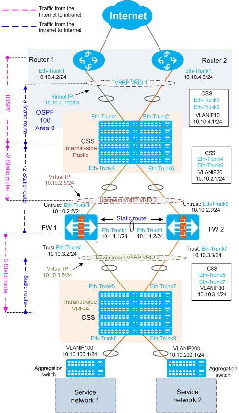
- When traffic from the intranet to the Internet reaches VRF-A, it is then forwarded to the firewalls based on the static route (next hop is the downstream VRRP virtual IP address of firewalls) configured on VRF-A.
- After filtering the traffic, the firewalls forward traffic to Public based on the static route (next hop is the CSS's VLANIF 20).
- Public forwards traffic to routers based on the static route (next hop is the router VRRP virtual IP address).
- The traffic from the Internet to the intranet reaches the routers, and is then forwarded to Public based on the OSPF routing table.
- Public forwards the traffic to firewalls based on the static route (next hop is the upstream VRRP virtual IP address of firewalls).
- After filtering the traffic, the firewalls forward traffic to VRF-A based on the static route (next hop is the CSS's VLANIF 30).
- VRF-A forwards the traffic to aggregation switches based on OSPF routing table, and then the aggregation switches forward the traffic to service networks.
Device Selection
This example applies to the following products and versions. If other products or versions are used, the configurations may vary. For details, see a related configuration manual.
Device Type |
Device Model |
Device Version |
|---|---|---|
Access router |
AR3600 series routers |
V200R007C00 |
Firewall |
USG9500 series firewalls |
V500R001C20 |
Core switches |
S12700 series switches |
V200R008C00 |
Aggregation switch |
S5720-EI series switches |
V200R008C00 |
Data Plan
Device |
Interface Number |
Member Interface |
VLANIF |
IP Address |
Remote Device |
Remote Interface Number |
|---|---|---|---|---|---|---|
Router1 |
Eth-trunk1.100 |
10GE1/0/1 10GE1/0/2 |
- |
10.10.4.2/24 |
Switch 1 Switch 2 |
Eth-Trunk1 |
Router2 |
Eth-trunk1.100 |
10GE1/0/1 10GE1/0/2 |
- |
10.10.4.3/24 |
Switch 1 Switch 2 |
Eth-Trunk2 |
VRRP of Router 1 and Router 2 |
- |
- |
- |
10.10.4.100/24 |
- |
- |
CSS (Switch 1 and Switch 2) |
Eth-trunk1 |
10GE1/4/0/0 10GE2/4/0/0 |
VLANIF10 |
10.10.4.1/24 |
Router 1 |
Eth-Trunk1 |
Eth-trunk2 |
10GE1/4/0/1 10GE2/4/0/1 |
VLANIF10 |
10.10.4.1/24 |
Router 2 |
Eth-Trunk1 |
|
Eth-trunk4 |
GE1/1/0/7 GE2/1/0/7 |
VLANIF20 |
10.10.2.1/24 |
FW 1 |
Eth-Trunk4 |
|
Eth-trunk5 |
GE1/1/0/8 GE2/1/0/8 |
VLANIF30 |
10.10.3.1/24 |
FW 1 |
Eth-Trunk5 |
|
Eth-trunk6 |
GE1/2/0/7 GE2/2/0/7 |
VLANIF20 |
10.10.2.1/24 |
FW 2 |
Eth-Trunk6 |
|
Eth-trunk7 |
GE1/2/0/8 GE2/2/0/8 |
VLANIF30 |
10.10.3.1/24 |
FW 2 |
Eth-Trunk7 |
|
Eth-trunk8 |
GE1/3/0/1 GE2/3/0/1 |
VLANIF100 |
10.10.100.1/24 |
Service network 1 |
- (omitted in this example) |
|
Eth-trunk9 |
GE1/3/0/2 GE2/3/0/2 |
VLANIF200 |
10.10.200.1/24 |
Service network 2 |
- (omitted in this example) |
|
FW1 |
Eth-trunk1 |
GE2/0/0 GE2/0/1 |
- |
10.1.1.1/24 |
FW2 |
Eth-Trunk1 |
Eth-Trunk4 |
GE1/0/0 GE1/0/1 |
- |
10.10.2.2/24 |
Switch 1 Switch 2 |
Eth-Trunk4 |
|
Eth-Trunk5 |
GE1/1/0 GE1/1/1 |
- |
10.10.3.2/24 |
Switch 1 Switch 2 |
Eth-Trunk5 |
|
FW2 |
Eth-trunk1 |
GE2/0/0 GE2/0/1 |
- |
10.1.1.2/24 |
FW1 |
Eth-Trunk1 |
Eth-Trunk6 |
GE1/0/0 GE1/0/1 |
- |
10.10.2.3/24 |
Switch 1 Switch 2 |
Eth-Trunk6 |
|
Eth-Trunk7 |
GE1/1/0 GE1/1/1 |
- |
10.10.3.3/24 |
Switch 1 Switch 2 |
Eth-Trunk7 |
|
VRRP1 of FW 1 and FW 2 (upstream) |
- |
- |
- |
10.10.2.5/24 |
- |
- |
VRRP2 of FW 1 and FW 2 (downstream) |
- |
- |
- |
10.10.3.5/24 |
- |
- |
Configuration Roadmap
The configuration roadmap is as follows:
Configure the CSS for core switches.
Assign IP addresses to the interfaces between switches, firewalls, and routers.
To improve link reliability, configure inter-chassis Eth-Trunks between switches and firewalls and between switches and routers.
Configure security zones on the firewalls' interfaces.
Configure VRRP on egress routers.
To ensure reliability between the core switches and two egress routers, deploy VRRP between the two egress routers so that VRRP heartbeat packets are exchanged through the core switches. Router1 functions as the master device, and Router2 functions as the backup device.
Deploy routing.
Configure the VRF function on switches to divide the CSS into a virtual switch VRF-A and a root switch Public, which separate the service network routes and public network routes.
To steer the upstream traffic on each device, configure a default route on core switches, of which the next hop is the VRRP virtual IP address of the egress routers.
To steer the return traffic of two egress routers, configure OSPF between the egress routers and core switches, and advertise all user network segment routes on the core switches into OSPF on egress routers.
To forward the upstream traffic of service networks to firewalls, configure a default route on switches, of which the next hop is the virtual IP address of VRRP VRID2 on firewalls.
To forward the downstream traffic of service network 1 to firewalls, configure a default route on switches, of which the next hop is the virtual IP address of VRRP VRID1 on firewalls.
To forward the downstream traffic of service network 2 to firewalls, configure a default route on switches, of which the next hop is the virtual IP address of VRRP VRID1 on firewalls.
To forward the upstream traffic of service networks to switches, configure a default route on firewalls, of which the next hop is the IP address of VLANIF 20 on switches.
To forward the downstream traffic of service network 1 to switches, configure a default route on firewalls, of which the next hop is the IP address of VLANIF 30 on switches.
To forward the downstream traffic of service network 2 to switches, configure a default route on firewalls, of which the next hop is the IP address of VLANIF 30 on switches.
Configure HRP on firewalls.
Procedure
- On switch 1 and switch 2: Configure CSSs.
- Connect CSS cards through cables.
In the following figure, the S12700 switches have the CSS cards EH1D2VS08000 installed. An S12700 has a maximum number of MPUs, SFUs, and CSS cards installed. Each chassis must have at least one MPU and one SFU installed. You are advised to install two SFUs and two CSS cards in each chassis.
Figure 4 CSS card connections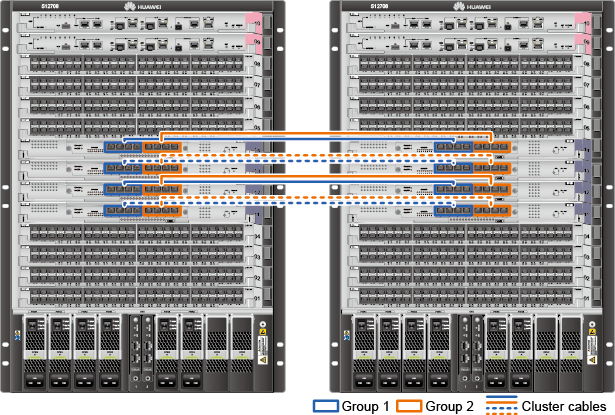

The two chassis are connected by at least one CSS cable.
- One CSS card can only be connected to one CSS card in the other chassis but not the local chassis.
- An interface in group 1 of a CSS card can only be connected to any interface in group 1 of the CSS card on the other chassis. The requirements for interfaces in group 2 are the same.
- CSS cards have the same number of cluster cables connected. (If the CSS cards have different numbers of cluster cables connected, the total cluster bandwidth depends on the cluster with the least cluster cables connected.) In addition, interfaces on CSS cards are connected based on interface numbers.
- Check the CSS status after the switches restart.
- On Switch 1, the active switch of the CSS, the MASTER indicator on the active MPU is steady green. (Figure 1)
- On Switch 1, the CSS ID indicators numbered 1 on both MPUs are steady green. On Switch 2, the CSS ID indicators numbered 2 on both MPUs are steady green. (Figure 1)
- The LINK/ALM indicators of interfaces on all CSS cards connected to cluster cables are steady green. (Figure 2)
- The MASTER indicators on all CSS cards in the active chassis are steady green, and the MASTER indicators on all CSS cards in the standby chassis are off. (Figure 2)
Figure 5 Indicators of the MPU and CSS card
- After the CSS is established, subsequent operations will be performed on the master switch (switch 1) and data will be automatically synchronized to the standby switch (switch 2).
- The interface name in a CSS is in the format like 10GE1/4/0/0. The leftmost part indicates the CSS ID.
- Connect CSS cards through cables.
- Configure the inter-chassis Eth-Trunks between CSS and FWs and between CSS and routers. Configure VLANIF interfaces on the CSS and assign IP addresses to them.
- On routers: Configure the interfaces between routers and CSS.
# Configure Router1, create Eth-Trunk1 on Router1, and add member interfaces to Eth-Trunk1.
<Huawei> system-view
[Huawei] sysname Router1
[Router1] interface Eth-Trunk 1
[Router1-Eth-Trunk1] quit
[Router1] interface XGigabitethernet 1/0/1
[Router1-XGigabitEthernet1/0/1] undo shutdown
[Router1-XGigabitEthernet1/0/1] Eth-Trunk 1
[Router1-XGigabitEthernet1/0/1] quit
[Router1] interface XGigabitethernet 1/0/2
[Router1-XGigabitEthernet1/0/2] undo shutdown
[Router1-XGigabitEthernet1/0/2] Eth-Trunk 1
[Router1-XGigabitEthernet1/0/2] quit
# Configure the Dot1q termination subinterface for VLAN 10 and assign an IP address to the subinterface.
[Router1] interface Eth-Trunk 1.100
[Router1-Eth-Trunk1.100] ip address 10.10.4.2 24
[Router1-Eth-Trunk1.100] dot1q termination vid 10
[Router1-Eth-Trunk1.100] quit
# The configuration procedure on Router2 is the same as that on Router1 except that the interface addresses are different.
- On firewalls: Configure interfaces and zones.
# Configure interfaces and zones on FW1.
<USG> system-view
[USG] sysname FW1
[FW1] interface Eth-Trunk 4   //Configure the interface connected to CSS and assign an IP address to it.
[FW1-Eth-Trunk4] ip address 10.10.2.2 24
[FW1-Eth-Trunk4] quit
[FW1] interface Gigabitethernet 1/0/0   //Add an interface to Eth-Trunk4.
[FW1-GigabitEthernet1/0/0] Eth-Trunk 4
[FW1-GigabitEthernet1/0/0] quit
[FW1] interface Gigabitethernet 1/0/1   //Add an interface to Eth-Trunk4.
[FW1-GigabitEthernet1/0/1] Eth-Trunk 4
[FW1-GigabitEthernet1/0/1] quit

[FW1] interface Eth-Trunk 5   //Configure the interface connected to CSS and assign an IP address to it.
[FW1-Eth-Trunk5] ip address 10.10.3.2 24
[FW1-Eth-Trunk5] quit
[FW1] interface Gigabitethernet 1/1/0   //Add an interface to Eth-Trunk5.
[FW1-GigabitEthernet1/1/0] Eth-Trunk 5
[FW1-GigabitEthernet1/1/0] quit
[FW1] interface Gigabitethernet 1/1/1   //Add an interface to Eth-Trunk5.
[FW1-GigabitEthernet1/1/1] Eth-Trunk 5
[FW1-GigabitEthernet1/1/1] quit

[FW1] interface Eth-Trunk 1   //Configure the interface connecting FW1 to FW2.
[FW1-Eth-Trunk1] ip address 10.1.1.1 24
[FW1-Eth-Trunk1] quit
[FW1] interface Gigabitethernet 2/0/0   //Add an interface to Eth-Trunk1.
[FW1-GigabitEthernet2/0/0] Eth-Trunk 1
[FW1-GigabitEthernet2/0/0] quit
[FW1] interface Gigabitethernet 2/0/1   //Add an interface to Eth-Trunk1.
[FW1-GigabitEthernet2/0/1] Eth-Trunk 1
[FW1-GigabitEthernet2/0/1] quit

[FW1] firewall zone trust
[FW1-zone-trust] add interface Eth-Trunk 5   //Add Eth-Trunk5 connected to the intranet to a trusted zone.
[FW1-zone-trust] quit
[FW1] firewall zone untrust
[FW1-zone-untrust] add interface Eth-Trunk 4   //Add Eth-Trunk4 connected to the extranet to an untrusted zone.
[FW1-zone-untrust] quit
[FW1] firewall zone dmz
[FW1-zone-dmz] add interface Eth-Trunk 1   //Add the interface between FW1 and FW2 to the DMZ.
[FW1-zone-dmz] quit
# Configure interfaces and zones on FW2.
<USG> system-view
[USG] sysname FW2
[FW2] interface Eth-Trunk 6   //Configure the interface connected to CSS and assign an IP address to it.
[FW2-Eth-Trunk6] ip address 10.10.2.3 24
[FW2-Eth-Trunk6] quit
[FW2] interface Gigabitethernet 1/0/0   //Add an interface to Eth-Trunk6.
[FW2-GigabitEthernet1/0/0] Eth-Trunk 6
[FW2-GigabitEthernet1/0/0] quit
[FW2] interface Gigabitethernet 1/0/1   //Add an interface to Eth-Trunk6.
[FW2-GigabitEthernet1/0/1] Eth-Trunk 6
[FW2-GigabitEthernet1/0/1] quit

[FW2] interface Eth-Trunk 7   //Configure the interface connected to CSS and assign an IP address to it.
[FW2-Eth-Trunk7] ip address 10.10.3.3 24
[FW2-Eth-Trunk7] quit
[FW2] interface Gigabitethernet 1/1/0   //Add an interface to Eth-Trunk7.
[FW2-GigabitEthernet1/1/0] Eth-Trunk 7
[FW2-GigabitEthernet1/1/0] quit
[FW2] interface Gigabitethernet 1/1/1   //Add an interface to Eth-Trunk7.
[FW2-GigabitEthernet1/1/1] Eth-Trunk 7
[FW2-GigabitEthernet1/1/1] quit

[FW2] interface Eth-Trunk 1   //Configure the interface between FW2 and FW1.
[FW2-Eth-Trunk1] ip address 10.1.1.2 24
[FW2-Eth-Trunk1] quit
[FW2] interface Gigabitethernet 2/0/0   //Add an interface to Eth-Trunk1.
[FW2-GigabitEthernet2/0/0] Eth-Trunk 1
[FW2-GigabitEthernet2/0/0] quit
[FW2] interface Gigabitethernet 2/0/1   //Add an interface to Eth-Trunk1.
[FW2-GigabitEthernet2/0/1] Eth-Trunk 1
[FW2-GigabitEthernet2/0/1] quit

[FW2] firewall zone trust
[FW2-zone-trust] add interface Eth-Trunk 7   //Add Eth-Trunk7 connected to the intranet to the trusted zone.
[FW2-zone-trust] quit
[FW2] firewall zone untrust
[FW2-zone-untrust] add interface Eth-Trunk 6   //Add Eth-Trunk6 connected to the extranet to the untrusted zone.
[FW2-zone-untrust] quit
[FW2] firewall zone dmz
[FW2-zone-dmz] add interface Eth-Trunk 1   //Add the interface between FW1 and FW2 to the DMZ.
[FW2-zone-dmz] quit
- On routers: Configure VRRP. Configure Router1 as the VRRP master and Router2 as the VRRP backup.
# Configure Router1.
[Router1] interface Eth-Trunk 1.100
[Router1-Eth-Trunk1.100] vrrp vrid 1 virtual-ip 10.10.4.100   //Configure the VRRP virtual IP address.
[Router1-Eth-Trunk1.100] vrrp vrid 1 priority 120   //Increase the priority of Router1 to make Router1 become the Master.
[Router1-Eth-Trunk1.100] quit
# Configure Router2.
[Router2] interface Eth-Trunk 1.100
[Router2-Eth-Trunk1.100] vrrp vrid 1 virtual-ip 10.10.4.100   //Configure the VRRP virtual IP address.
[Router2-Eth-Trunk1.100] quit
After the configuration is complete, a VRRP group should have been set up between Router1 and Router2. You can run the display vrrp command to view the VRRP status of Router1 and Router2.
# Check the VRRP status of Router1. The status is master.
[Router1] display vrrp
  Eth-Trunk1.100 | Virtual Router 1
    State : Master
    Virtual IP : 10.10.4.100
    Master IP : 10.10.4.2
    PriorityRun : 120
    PriorityConfig : 120
    MasterPriority : 120
    Preempt : YES   Delay Time : 0 s
    TimerRun : 1 s
    TimerConfig : 1 s
    Auth type : NONE
    Virtual MAC : 0000-5e00-0101
    Check TTL : YES
    Config type : normal-vrrp
    Create time : 2015-05-18 06:53:47 UTC-05:13
    Last change time : 2015-05-18 06:54:14 UTC-05:13
# Check the VRRP status of Router2. The status is backup.
[Router2] display vrrp Eth-Trunk1.100 | Virtual Router 1 State : Backup Virtual IP : 10.10.4.100 Master IP : 10.10.4.2 PriorityRun : 100 PriorityConfig : 100 MasterPriority : 120 Preempt : YES Delay Time : 0 s TimerRun : 1 s TimerConfig : 1 s Auth type : NONE Virtual MAC : 0000-5e00-0101 Check TTL : YES Config type : normal-vrrp Create time : 2015-05-18 06:53:52 UTC-05:13 Last change time : 2015-05-18 06:57:12 UTC-05:13 - Configure routes between CSS and FWs and between CSS and routers.
- Configure HRP on firewalls.
# Configure HRP on FW1 and set FW1 as master.
[FW1] interface Eth-Trunk 4
[FW1-Eth-Trunk4] vrrp vrid 1 virtual-ip 10.10.2.5 24 master   //Configure VRRP group 1 on the upstream interface and set it status to master.
[FW1-Eth-Trunk4] quit
[FW1] interface Eth-Trunk 5
[FW1-Eth-Trunk5] vrrp vrid 2 virtual-ip 10.10.3.5 24 master   //Configure VRRP group 2 on the downstream interface and set it status to master.
[FW1-Eth-Trunk5] quit
[FW1] hrp interface Eth-Trunk 1 remote 10.1.1.2   //Configure the heartbeat interface and enable HRP.
[FW1] firewall packet-filter default permit interzone local dmz
[FW1] hrp enable
HRP_M[FW1]
# Configure HRP on FW2 and set FW2 as slave.
[FW2] interface Eth-Trunk 6
[FW2-Eth-Trunk6] vrrp vrid 1 virtual-ip 10.10.2.5 24 slave   //Configure VRRP group 1 on the upstream interface and set it status to slave.
[FW2-Eth-Trunk6] quit
[FW2] interface Eth-Trunk 7
[FW2-Eth-Trunk7] vrrp vrid 2 virtual-ip 10.10.3.5 24 slave    //Configure VRRP group 2 on the downstream interface and set it status to slave.
[FW2-Eth-Trunk7] quit
[FW2] hrp interface Eth-Trunk 1 remote 10.1.1.1   //Configure the heartbeat interface and enable HRP.
[FW2] firewall packet-filter default permit interzone local dmz
[FW2] hrp enable
HRP_M[FW2]
# Check VRRP status. FW1 is the master and FW2 is the slave.
HRP_M[FW1] display vrrp
  Eth-Trunk4 | Virtual Router 1
     VRRP Group : Master
    State : Master
    Virtual IP : 10.10.2.5
    Virtual MAC : 0000-5e00-0101
    Primary IP : 10.10.2.2
    PriorityRun : 120
    PriorityConfig : 100
    MasterPriority : 120
    Preempt : YES   Delay Time : 0 s
     Advertisement Timer : 1
    Auth type : NONE
    Check TTL : YES

Eth-Trunk5 | Virtual Router 2
     VRRP Group : Master
    State : Master
    Virtual IP : 10.10.3.5
    Virtual MAC : 0000-5e00-0102
    Primary IP : 10.10.3.2
    PriorityRun : 120
    PriorityConfig : 100
    MasterPriority : 120
    Preempt : YES   Delay Time : 0 s
     Advertisement Timer : 1
    Auth type : NONE
    Check TTL : YES
HRP_M[FW2] display vrrp Eth-Trunk7 | Virtual Router 2 VRRP Group : Slave State : Backup Virtual IP : 10.10.3.5 Virtual MAC : 0000-5e00-0102 Primary IP : 10.10.3.3 PriorityRun : 100 PriorityConfig : 100 MasterPriority : 120 Preempt : YES Delay Time : 0 s Advertisement Timer : 1 Auth type : NONE Check TTL : YES Eth-Trunk6 | Virtual Router 1 VRRP Group : Slave State : Backup Virtual IP : 10.10.2.5 Virtual MAC : 0000-5e00-0101 Primary IP : 10.10.2.3 PriorityRun : 120 PriorityConfig : 100 MasterPriority : 120 Preempt : YES Delay Time : 0 s Advertisement Timer : 1 Auth type : NONE Check TTL : YES# Check HRP status.HRP_M[FW1] display hrp state The firewall's config state is: MASTER Current state of virtual routers configured as master: Eth-Trunk4 vrid 1 : master (gigabitEthernet1/0/0) : up (gigabitEthernet1/0/1) : up Eth-Trunk5 vrid 2 : master (gigabitEthernet1/1/0) : up (gigabitEthernet1/1/1) : up After HRP is configured, the configurations and sessions on the active firewall are synchronized to the standby firewall; therefore, you only need to perform the following configurations on the active firewall FW1.
- Configure security policies on firewalls.
Only the connection configurations between firewalls and switches and the HRP configurations on firewalls are provided in the following procedure. For the security service plan on the firewalls and security policies, attack defense, bandwidth management, and IPSec on the campus network, see Firewall Configuration Examples.
- Verify the configuration.
After the configurations are complete, check whether the CSS and routers can ping each other.
# Ping Eth-Trunk1.100 of Router1 from the CSS to check the uplink connectivity.
<CSS> ping 10.10.4.2

Ping 10.10.4.2: 32 data bytes, Press Ctrl_C to break
    Reply From 10.10.4.2: bytes=32 seq=1 ttl=126 time=140 ms
    Reply From 10.10.4.2: bytes=32 seq=2 ttl=126 time=235 ms
    Reply From 10.10.4.2: bytes=32 seq=3 ttl=126 time=266 ms
    Reply From 10.10.4.2: bytes=32 seq=4 ttl=126 time=140 ms
    Reply From 10.10.4.2: bytes=32 seq=5 ttl=126 time=141 ms

--- 10.10.200.2 ping statistics ---
  5 packet(s) transmitted
  5 packet(s) received
  0.00% packet loss
  round-trip min/avg/max = 140/184/266 ms
You can find that the CSS and Router1 can ping each other.
# Ping the VRF-A VLANIF 100 on the CSS from Router1 to check the downlink connectivity.
<Router1> Ping 10.10.100.1

Ping 10.10.100.1: 32 data bytes, Press Ctrl_C to break
    Reply From 10.10.100.1: bytes=32 seq=1 ttl=253 time=235 ms
    Reply From 10.10.100.1: bytes=32 seq=2 ttl=253 time=109 ms
    Reply From 10.10.100.1: bytes=32 seq=3 ttl=253 time=79 ms
    Reply From 10.10.100.1: bytes=32 seq=4 ttl=253 time=63 ms
    Reply From 10.10.100.1: bytes=32 seq=5 ttl=253 time=63 ms

--- 10.10.100.1 ping statistics ---
  5 packet(s) transmitted
  5 packet(s) received
  0.00% packet loss
  round-trip min/avg/max = 63/109/235 ms
You can find that Router1 and CSS VLANIF 100 can ping each other.
Configuration Files
Router1 configuration file
#
sysname Router1
#
interface Eth-Trunk1
#
interface Eth-Trunk1.100
 dot1q termination vid 10
 ip address 10.10.4.2 255.255.255.0
 vrrp vrid 1 virtual-ip 10.10.4.100
 vrrp vrid 1 priority 120
#
interface XGigabitEthernet1/0/1
 eth-trunk 1
#
interface XGigabitEthernet1/0/2
 eth-trunk 1
#
ospf 100 router-id 2.2.2.2
 area 0.0.0.0
  network 10.10.4.0 0.0.0.255
#
return
Router2 configuration file
#
sysname Router2
#
interface Eth-Trunk1
#
interface Eth-Trunk1.100
 dot1q termination vid 10
 ip address 10.10.4.3 255.255.255.0
 vrrp vrid 1 virtual-ip 10.10.4.100
#
interface XGigabitEthernet1/0/1
 eth-trunk 1
#
interface XGigabitEthernet1/0/2
 eth-trunk 1
#
ospf 100 router-id 3.3.3.3
 area 0.0.0.0
  network 10.10.4.0 0.0.0.255
#
return
CSS configuration file
#
 sysname CSS
#
vlan batch 10 20 30 100 200
#
ip vpn-instance Public
 ipv4-family
  route-distinguisher 100:2
  vpn-target 222:2 export-extcommunity
  vpn-target 222:2 import-extcommunity
#
ip vpn-instance VRF-A
 ipv4-family
  route-distinguisher 100:1
  vpn-target 111:1 export-extcommunity
  vpn-target 111:1 import-extcommunity

#
interface Vlanif1
#
interface Vlanif10
 ip binding vpn-instance Public
 ip address 10.10.4.1 255.255.255.0
#
interface Vlanif20
 ip binding vpn-instance Public
 ip address 10.10.2.1 255.255.255.0
#
interface Vlanif30
 ip binding vpn-instance VRF-A
 ip address 10.10.3.1 255.255.255.0
#
interface Vlanif100
 ip binding vpn-instance VRF-A
 ip address 10.10.100.1 255.255.255.0
#
interface Vlanif200
 ip binding vpn-instance VRF-A
 ip address 10.10.200.1 255.255.255.0
#
interface Eth-Trunk1
 port link-type trunk
 port trunk allow-pass vlan 10
#
interface Eth-Trunk2
 port link-type trunk
 port trunk allow-pass vlan 10
#
interface Eth-Trunk4
 port link-type trunk
 port trunk allow-pass vlan 20
#
interface Eth-Trunk5
 port link-type trunk
 port trunk allow-pass vlan 30
#
interface Eth-Trunk6
 port link-type trunk
 port trunk allow-pass vlan 20
#
interface Eth-Trunk7
 port link-type trunk
 port trunk allow-pass vlan 30
#
interface Eth-Trunk8
 port link-type trunk
 port trunk allow-pass vlan 100
#
interface Eth-Trunk9
 port link-type trunk
 port trunk allow-pass vlan 200
#
interface Eth-Trunk1.100
 dot1q termination vid 100
 ip address 10.10.100.3 255.255.255.0
 vrrp vrid 1 virtual-ip 10.10.100.1
 arp broadcast enable
#
interface GigabitEthernet1/1/0/7
  eth-trunk 4
#
interface GigabitEthernet1/1/0/8
  eth-trunk 5
#
interface GigabitEthernet1/2/0/7
  eth-trunk 6
#
interface GigabitEthernet1/2/0/8
  eth-trunk 7
#
interface GigabitEthernet1/3/0/1
  eth-trunk 8
#
interface GigabitEthernet1/3/0/2
  eth-trunk 9
#
interface GigabitEthernet2/1/0/7
  eth-trunk 4
#
interface GigabitEthernet2/1/0/8
  eth-trunk 5
#
interface GigabitEthernet2/2/0/7
  eth-trunk 6
#
interface GigabitEthernet2/2/0/8
  eth-trunk 7
#
interface GigabitEthernet2/3/0/1
  eth-trunk 8
#
interface GigabitEthernet2/3/0/2
  eth-trunk 9
#
interface XGigabitEthernet1/4/0/0
 eth-trunk 1
#
interface XGigabitEthernet1/4/0/1
 eth-trunk 2
#
interface XGigabitEthernet2/4/0/0
 eth-trunk 1
#
interface XGigabitEthernet2/4/0/1
 eth-trunk 2
#
ospf 100 router-id 1.1.1.1 vpn-instance Public
 import-route static
 area 0.0.0.0
   network 10.10.4.0 0.0.0.255
#
ip route-static vpn-instance VRF-A 0.0.0.0 0.0.0.0 10.10.3.5
ip route-static vpn-instance Public 0.0.0.0 0.0.0.0 10.10.4.100
ip route-static vpn-instance Public 10.10.100.0 255.255.255.0 10.10.2.5
ip route-static vpn-instance Public 10.10.200.0 255.255.255.0 10.10.2.5
#
return
FW1 configuration file
#
interface Eth-Trunk1
 alias Eth-Trunk1
 ip address 10.1.1.1 255.255.255.0
#
interface Eth-Trunk4
 alias Eth-Trunk4
 ip address 10.10.2.2 255.255.255.0
 vrrp vrid 1 virtual-ip 10.10.2.5 master
#
interface Eth-Trunk5
 alias Eth-Trunk5
 ip address 10.10.3.2 255.255.255.0
 vrrp vrid 2 virtual-ip 10.10.3.5 master
#
interface GigabitEthernet0/0/0
 alias GE0/MGMT
 ip address 192.168.0.1 255.255.255.0
 dhcp select interface
 dhcp server gateway-list 192.168.0.1
#
interface GigabitEthernet1/0/0
 undo enable snmp trap updown physic-status
 eth-trunk 4
#
interface GigabitEthernet1/0/1
 undo enable snmp trap updown physic-status
 eth-trunk 4
#
interface GigabitEthernet1/1/0
 undo enable snmp trap updown physic-status
 eth-trunk 5
#
interface GigabitEthernet1/1/1
 undo enable snmp trap updown physic-status
 eth-trunk 5
#
interface GigabitEthernet2/0/0
 undo enable snmp trap updown physic-status
 eth-trunk 1
#
interface GigabitEthernet2/0/1
 undo enable snmp trap updown physic-status
 eth-trunk 1
#
firewall zone local
 set priority 100
#
firewall zone trust
 set priority 85
 add interface Eth-Trunk5
 add interface GigabitEthernet0/0/0
#
firewall zone untrust
 set priority 5
add interface Eth-Trunk4
#
firewall zone dmz
 set priority 50
 add interface Eth-Trunk1
#
 ip route-static 0.0.0.0 0.0.0.0 10.10.2.1
 ip route-static 10.10.100.0 255.255.255.0 10.10.3.1
 ip route-static 10.10.200.0 255.255.255.0 10.10.3.1
#
 sysname FW1
#
 hrp enable
 hrp interface Eth-Trunk1 remote 10.1.1.2
#
 firewall packet-filter default permit interzone local trust direction inbound
 firewall packet-filter default permit interzone local trust direction outbound
 firewall packet-filter default permit interzone local untrust direction outbound

 firewall packet-filter default permit interzone local dmz direction inbound
 firewall packet-filter default permit interzone local dmz direction outbound
#
return
FW2 configuration file
#
interface Eth-Trunk1
 alias Eth-Trunk1
 ip address 10.1.1.2 255.255.255.0
#
interface Eth-Trunk6
 alias Eth-Trunk6
 ip address 10.10.2.3 255.255.255.0
 vrrp vrid 1 virtual-ip 10.10.2.5 slave
#
interface Eth-Trunk7
 alias Eth-Trunk7
 ip address 10.10.3.30 255.255.255.0
 vrrp vrid 2 virtual-ip 10.10.3.5 255.255.255.0 slave
#
interface GigabitEthernet0/0/0
 alias GE0/MGMT
 ip address 192.168.0.1 255.255.255.0
 dhcp select interface
 dhcp server gateway-list 192.168.0.1
#
interface GigabitEthernet1/0/0
 undo enable snmp trap updown physic-status
 eth-trunk 6
#
interface GigabitEthernet1/0/1
 undo enable snmp trap updown physic-status
 eth-trunk 6
#
interface GigabitEthernet1/1/0
 undo enable snmp trap updown physic-status
 eth-trunk 7
#
interface GigabitEthernet1/1/1
 undo enable snmp trap updown physic-status
 eth-trunk 7
#
interface GigabitEthernet2/0/0
 undo enable snmp trap updown physic-status
 eth-trunk 1
#
interface GigabitEthernet2/0/1
 undo enable snmp trap updown physic-status
 eth-trunk 1
#
firewall zone local
 set priority 100
#
firewall zone trust
 set priority 85
 add interface Eth-Trunk7
 add interface GigabitEthernet0/0/0
#
firewall zone untrust
 set priority 5
add interface Eth-Trunk6
#
firewall zone dmz
 set priority 50
 add interface Eth-Trunk1
#
 ip route-static 0.0.0.0 0.0.0.0 10.10.2.1
 ip route-static 10.10.100.0 255.255.255.0 10.10.3.1
 ip route-static 10.10.200.0 255.255.255.0 10.10.3.1
#
 sysname FW2
#
hrp enable
 hrp interface Eth-Trunk1 remote 10.1.1.1
#
 firewall packet-filter default permit interzone local trust direction inbound
 firewall packet-filter default permit interzone local trust direction outbound
 firewall packet-filter default permit interzone local untrust direction outbound

 firewall packet-filter default permit interzone local dmz direction inbound
 firewall packet-filter default permit interzone local dmz direction outbound
#
return