Example for Configuring a DHCP Server to Allocate IP Addresses to IP Phones
Networking Requirements
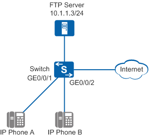
In Figure 1, IP phones send tagged voice packets. High-quality VoIP service voice data flows must be transmitted with a high priority to ensure call quality. To simplify management, the enterprise administrator requires that a DHCP server be deployed to allocate IP addresses to IP phones. Each IP phone also needs to dynamically obtain its startup configuration file configuration.ini from the FTP server. There are reachable routes between the FTP server and IP phones.
Configuration Roadmap
- Configure a voice VLAN on the Switch to ensure that the Switch preferentially forwards voice packets.
- Configure the Switch as a DHCP server to dynamically allocate the voice VLAN, startup configuration file, and IP addresses to IP phones.
Procedure
- Create VLAN 10 and add GE0/0/1 and GE0/0/2 to VLAN 10.
<HUAWEI> system-view
[HUAWEI] sysname Switch
[Switch] vlan 10
[Switch-vlan10] quit
[Switch] interface gigabitethernet 0/0/1
[Switch-GigabitEthernet0/0/1] port link-type trunk
[Switch-GigabitEthernet0/0/1] port trunk pvid vlan 10
[Switch-GigabitEthernet0/0/1] port trunk allow-pass vlan 10
[Switch-GigabitEthernet0/0/1] quit
[Switch] interface gigabitethernet 0/0/2
[Switch-GigabitEthernet0/0/2] port link-type trunk
[Switch-GigabitEthernet0/0/2] port trunk pvid vlan 10
[Switch-GigabitEthernet0/0/2] port trunk allow-pass vlan 10
[Switch-GigabitEthernet0/0/2] quit
- Configure a voice VLAN to increase priority of voice packets.
[Switch] interface gigabitethernet 0/0/1
[Switch-GigabitEthernet0/0/1] voice-vlan 10 enable
[Switch-GigabitEthernet0/0/1] voice-vlan remark-mode vlan
[Switch-GigabitEthernet0/0/1] quit
[Switch] interface gigabitethernet 0/0/2
[Switch-GigabitEthernet0/0/2] voice-vlan 10 enable
[Switch-GigabitEthernet0/0/2] voice-vlan remark-mode vlan
[Switch-GigabitEthernet0/0/2] quit
# Run the display voice-vlan 10 status command to check whether the configuration of the voice VLAN is correct.
[Switch] display voice-vlan 10 status
Voice VLAN Configurations:
-----------------------------------------------------------
Voice VLAN ID            : 10
Voice VLAN status        : Enable
Voice VLAN 8021p remark  : 6
Voice VLAN dscp remark   : 46
-----------------------------------------------------------
Port Information:
-------------------------------------------------------------------------------------------
Port                       Add-Mode  Security-Mode  Legacy  PribyVLAN  Untag   Tag0
-------------------------------------------------------------------------------------------
GigabitEthernet0/0/2       Manual    Normal         Disable Enable     Disable Disable
GigabitEthernet0/0/1       Manual    Normal         Disable Enable     Disable Disable

Only the S5720-EI, S6720-EI, and S6720S-EI support the Tag0 field.
- Configure the Switch as a DHCP server to dynamically allocate the voice VLAN, startup configuration file, and IP addresses to IP phones.
# Enable DHCP.
[Switch] dhcp enable
# Configure VLANIF 10 to work in interface address pool mode. Configure the voice VLAN, startup configuration file, and allocatable IP address range in this address pool.
[Switch] interface vlanif 10
[Switch-Vlanif10] ip address 10.1.1.1 24
[Switch-Vlanif10] dhcp select interface
[Switch-Vlanif10] dhcp server bootfile configuration.ini
[Switch-Vlanif10] dhcp server next-server 10.1.1.3
[Switch-Vlanif10] dhcp server option184 voice-vlan 10
[Switch-Vlanif10] quit
The DHCP server is configured to allocate Option 184, which delivers the VLAN ID to IP phones so that packets sent by IP phones carry the same VLAN ID as that configured on the DHCP server. IP phone vendors may define different values for the Option field. For details about the options, see the usage guide of the IP phones.
- Verify the configuration.
# Run the display ip pool interface vlanif10 command on the Switch to view the address pool configuration.
[Switch] display ip pool interface vlanif10
  Pool-name      : Vlanif10
  Pool-No        : 0
  Lease          : 1 Days 0 Hours 0 Minutes
  Next-server    : 10.1.1.3
  Domain-name    : -
  Option-code    : 184
    Option-subcode : --
    Option-type    : hex
    Option-value   : 0302000A
  DNS-server0    : -
  NBNS-server0   : -
  Netbios-type   : -
  Position       : Interface
  Status         : Unlocked
  Gateway-0      : 10.1.1.1
  Network        : 10.1.1.0
  Mask           : 255.255.255.0
  VPN instance   : --
  Bootfile       : configuration.ini
  Logging        : Disable
  Conflicted address recycle interval: -
  Address Statistic: Total       :253       Used        :2
                     Idle        :251       Expired     :0
                     Conflict    :0         Disabled     :0

 -----------------------------------------------------------------------------
  Network section
         Start           End     Total  Used  Idle(Expired)  Conflict  Disabled
 -----------------------------------------------------------------------------
      10.20.20.1    10.20.20.254   253     2        251(0)         0        0
 -----------------------------------------------------------------------------
Configuration Files
Switch configuration file
#
sysname Switch
#
vlan batch 10
#
dhcp enable
#
interface Vlanif10
 ip address 10.1.1.1 255.255.255.0
 dhcp select interface
 dhcp server next-server 10.1.1.3
 dhcp server option184 voice-vlan 10
 dhcp server bootfile configuration.ini
#
interface GigabitEthernet0/0/1
 port link-type trunk
 voice-vlan 10 enable
 port trunk pvid vlan 10
 port trunk allow-pass vlan 10
#
interface GigabitEthernet0/0/2
 port link-type trunk
 voice-vlan 10 enable
 port trunk pvid vlan 10
 port trunk allow-pass vlan 10
#
return