Example for Configuring a DHCP Server in a Super-VLAN
Networking Requirements
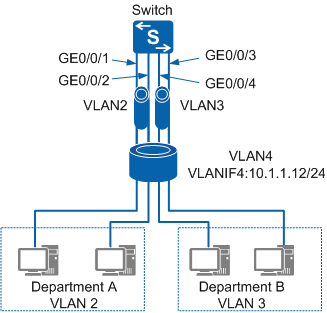
In Figure 1, an enterprise has two departments that are allocated the same network segment to conserve IP address resources. Users in departments A and B belong to different VLANs for higher security and must be able to communicate at Layer 3. For unified management, a DHCP server must be deployed to dynamically allocate IP addresses to terminals in the departments.

Only the S5720-EI, S5720-HI, S5720I-SI, S5720S-SI, S5720-SI, S5735-S, S5735S-S, S5735-S-I, S5730-HI, S5730S-EI, S5730-SI, S5731-H, S5731S-H, S5731-S, S5731S-S, S6720-HI, S6720S-SI, S6720-SI, S5732-H, S6730-H, S6730S-H, S6730-S, S6730S-S, S6720-EI, and S6720S-EI support super-VLANs.
Configuration Roadmap
Configure sub-VLANs on the Switch to implement Layer 2 isolation between users in different sub-VLANs. The sub-VLANs are on the same network segment, which reduces the amount of required IP address resources.
Configure proxy ARP on the VLANIF interface of the super-VLAN to implement Layer 3 communication among sub-VLANs.
Configure a DHCP server in the super-VLAN to dynamically allocate IP addresses to terminals in departments A and B.
Procedure
- Create VLAN 2, and add GE0/0/1 and GE0/0/2 to VLAN 2. Create VLAN 3, and add GE0/0/3 and GE0/0/4 to VLAN 3.
<HUAWEI> system-view
[HUAWEI] sysname Switch
[Switch] vlan batch 2 to 4
[Switch] interface GigabitEthernet 0/0/1
[Switch-GigabitEthernet0/0/1] port link-type access
[Switch-GigabitEthernet0/0/1] port default vlan 2
[Switch-GigabitEthernet0/0/1] quit
[Switch] interface GigabitEthernet 0/0/2
[Switch-GigabitEthernet0/0/2] port link-type access
[Switch-GigabitEthernet0/0/2] port default vlan 2
[Switch-GigabitEthernet0/0/2] quit
[Switch] interface GigabitEthernet 0/0/3
[Switch-GigabitEthernet0/0/3] port link-type access
[Switch-GigabitEthernet0/0/3] port default vlan 3
[Switch-GigabitEthernet0/0/3] quit
[Switch] interface GigabitEthernet 0/0/4
[Switch-GigabitEthernet0/0/4] port link-type access
[Switch-GigabitEthernet0/0/4] port default vlan 3
[Switch-GigabitEthernet0/0/4] quit
- Configure a super-VLAN to implement VLAN aggregation.
# Configure the super-VLAN.
[Switch] vlan 4
[Switch-vlan4] aggregate-vlan
[Switch-vlan4] access-vlan 2 to 3
[Switch-vlan4] quit
# Configure the VLANIF interface.
[Switch] interface vlanif 4
[Switch-Vlanif4] ip address 10.1.1.12 255.255.255.0
[Switch-Vlanif4] quit
- Configure proxy ARP.
[Switch] interface vlanif 4
[Switch-Vlanif4] arp-proxy inter-sub-vlan-proxy enable
[Switch-Vlanif4] quit
- Configure a DHCP server based on the interface address pool on VLANIF 4 to dynamically allocate IP addresses to terminals in sub-VLANs.
[Switch] dhcp enable
[Switch] interface vlanif 4
[Switch-Vlanif4] dhcp select interface
[Switch-Vlanif4] quit
- Verify the configuration.
After the configuration is complete, run the display ip pool interface vlanif4 command on the Switch to view IP address allocation in the address pool. The Used field displays the number of used IP addresses in the address pool.
[Switch] display ip pool interface vlanif4
  Pool-name        : Vlanif4
  Pool-No          : 0
  Lease            : 1 Days 0 Hours 0 Minutes
  Domain-name      : -
  DNS-server0      : -
  NBNS-server0     : -
  Netbios-type     : -
  Position         : Interface
  Status           : Unlocked
  Gateway-0        : 10.1.1.12
  Network          : 10.1.1.0
  Mask             : 255.255.255.0
  VPN instance     : --
  Logging          : Disable
  Conflicted address recycle interval: -
  Address Statistic: Total       :253       Used        :4
                     Idle        :249       Expired     :0
                     Conflict    :0         Disabled     :0

 -------------------------------------------------------------------------------
  Network section
         Start           End       Total    Used Idle(Expired) Conflict Disabled
 -------------------------------------------------------------------------------
      10.1.1.1      10.1.1.254     253       4        249(0)       0     0
 -------------------------------------------------------------------------------
Configuration Files
Switch configuration file
#
sysname Switch
#
vlan batch 2 to 4
#
dhcp enable
#
vlan 4
 aggregate-vlan
 access-vlan 2 to 3
#
interface Vlanif4
 ip address 10.1.1.12 255.255.255.0
 arp-proxy inter-sub-vlan-proxy enable
 dhcp select interface
#
interface GigabitEthernet0/0/1
 port link-type access
 port default vlan 2
#
interface GigabitEthernet0/0/2
 port link-type access
 port default vlan 2
#
interface GigabitEthernet0/0/3
 port link-type access
 port default vlan 3
#
interface GigabitEthernet0/0/4
 port link-type access
 port default vlan 3
#
return