Example for Configuring DHCP Servers on the Same Network Segment (Based on the Global Address Pool in VRRP Networking)
Networking Requirements
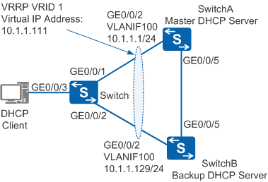
In Figure 1, a host in an enterprise is dual-homed to SwitchA and SwitchB through the Switch. SwitchA functions as the master DHCP server to allocate IP addresses to clients. If the master DHCP server fails, a backup DHCP server must allocate IP addresses to clients.
Configuration Roadmap
The configuration roadmap is as follows:
- Configure IP addresses for interfaces connecting SwitchA and SwitchB to implement network-layer connectivity. Configure the Switch to transparently transmit Layer 2 packets.
- Configure a VRRP group on SwitchA and SwitchB. SwitchA has a higher priority and functions as the master DHCP server to allocate IP addresses to clients. SwitchB has a lower priority and functions as a backup DHCP server.
- Create global address pools on SwitchA and SwitchB and set attributes for the pools.
- Configure a loop prevention protocol (STP used as an example) on Switch, SwitchA, and SwitchB
Procedure
- Configure network-layer connectivity among devices.
# Configure IP addresses for interfaces. The following uses SwitchA as an example. The configuration of SwitchB is similar. For details, see the configuration file of SwitchB.
<HUAWEI> system-view
[HUAWEI] sysname SwitchA
[SwitchA] vlan batch 100
[SwitchA] interface gigabitethernet 0/0/2
[SwitchA-GigabitEthernet0/0/2] port link-type hybrid
[SwitchA-GigabitEthernet0/0/2] port hybrid pvid vlan 100
[SwitchA-GigabitEthernet0/0/2] port hybrid untagged vlan 100
[SwitchA-GigabitEthernet0/0/2] quit
[SwitchA] interface gigabitethernet 0/0/5
[SwitchA-GigabitEthernet0/0/5] port link-type hybrid
[SwitchA-GigabitEthernet0/0/5] port hybrid pvid vlan 100
[SwitchA-GigabitEthernet0/0/5] port hybrid untagged vlan 100
[SwitchA-GigabitEthernet0/0/5] quit
[SwitchA] interface vlanif 100
[SwitchA-Vlanif100] ip address 10.1.1.1 24
[SwitchA-Vlanif100] quit
# Configure Layer 2 transparent transmission on Switch.
<HUAWEI> system-view
[HUAWEI] sysname Switch
[Switch] vlan 100
[Switch-vlan100] quit
[Switch] interface gigabitethernet 0/0/1
[Switch-GigabitEthernet0/0/1] port link-type hybrid
[Switch-GigabitEthernet0/0/1] port hybrid pvid vlan 100
[Switch-GigabitEthernet0/0/1] port hybrid untagged vlan 100
[Switch-GigabitEthernet0/0/1] quit
[Switch] interface gigabitethernet 0/0/2
[Switch-GigabitEthernet0/0/2] port link-type hybrid
[Switch-GigabitEthernet0/0/2] port hybrid pvid vlan 100
[Switch-GigabitEthernet0/0/2] port hybrid untagged vlan 100
[Switch-GigabitEthernet0/0/2] quit
[Switch] interface gigabitethernet 0/0/3
[Switch-GigabitEthernet0/0/3] port link-type access
[Switch-GigabitEthernet0/0/3] port default vlan 100
[Switch-GigabitEthernet0/0/3] quit
- Create address pools and set attributes for the pools.
# Enable DHCP on SwitchA.
[SwitchA] dhcp enable
# Create an address pool on SwitchA and specify an IP address range 10.1.1.2 to 10.1.1.128, which is exclusive from the IP address range of the address pool on SwitchB.

Information about the address pool on the master DHCP server cannot be backed up to a backup DHCP server in real time. To prevent IP address conflicts after a master/backup switchover, the address pool ranges on the master and backup DHCP servers must be mutually exclusive.
[SwitchA] ip pool 1
[SwitchA-ip-pool-1] network 10.1.1.0 mask 255.255.255.0
[SwitchA-ip-pool-1] gateway-list 10.1.1.111
[SwitchA-ip-pool-1] excluded-ip-address 10.1.1.1
[SwitchA-ip-pool-1] excluded-ip-address 10.1.1.129 10.1.1.254
[SwitchA-ip-pool-1] lease day 10
[SwitchA-ip-pool-1] quit
# Create an address pool on SwitchB and specify an IP address range 10.1.1.130 to 10.1.1.254, which is exclusive from the IP address range of the address pool on SwitchA.
[SwitchB] dhcp enable
[SwitchB] ip pool 1
[SwitchB-ip-pool-1] network 10.1.1.0 mask 255.255.255.0
[SwitchB-ip-pool-1] gateway-list 10.1.1.111
[SwitchB-ip-pool-1] excluded-ip-address 10.1.1.1 10.1.1.110
[SwitchB-ip-pool-1] excluded-ip-address 10.1.1.112 10.1.1.129
[SwitchB-ip-pool-1] lease day 10
[SwitchB-ip-pool-1] quit
- Configure a VRRP group.
# Create VRRP group 1 on SwitchA, set the priority of SwitchA in the VRRP group to 120, and configure clients to obtain IP addresses from a global address pool.
[SwitchA] interface vlanif 100
[SwitchA-Vlanif100] vrrp vrid 1 virtual-ip 10.1.1.111
[SwitchA-Vlanif100] vrrp vrid 1 priority 120
[SwitchA-Vlanif100] dhcp select global
[SwitchA-Vlanif100] quit
# Create VRRP group 1 on SwitchB, retain the priority (100 by default) of SwitchB in the VRRP group, and configure clients to obtain IP addresses from a global address pool.
[SwitchB] interface vlanif 100
[SwitchB-Vlanif100] vrrp vrid 1 virtual-ip 10.1.1.111
[SwitchB-Vlanif100] dhcp select global
[SwitchB-Vlanif100] quit
- Configure STP to prevent loops.
# Enable STP globally on Switch. The configurations on SwitchA and SwitchB are similar. For details, see the configuration files of SwitchA and SwitchB.
[Switch] stp enable
# Disable STP on GE0/0/3 of Switch, and set the path cost of GE0/0/1 to 20000.
[Switch] interface gigabitethernet 0/0/3
[Switch-GigabitEthernet0/0/3] stp disable
[Switch-GigabitEthernet0/0/3] quit
[Switch] interface gigabitethernet 0/0/1
[Switch-GigabitEthernet0/0/1] stp cost 20000
[Switch-GigabitEthernet0/0/1] quit
- Verify the configuration.
# Run the display vrrp command on SwitchA and SwitchB. The command output shows that SwitchA is the master and SwitchB is the backup in the VRRP group.
[SwitchA] display vrrp
  Vlanif100 | Virtual Router 1
    State : Master
    Virtual IP : 10.1.1.111
    Master IP : 10.1.1.1
    PriorityRun : 120
    PriorityConfig : 120
    MasterPriority : 120
    Preempt : YES   Delay Time : 0 s
    TimerRun : 1 s
    TimerConfig : 1 s
    Auth type : NONE
    Virtual MAC : 0000-5e00-0101
    Check TTL : YES
    Config type : normal-vrrp
    Backup-forward : disabled
    Create time : 2012-01-12 20:15:46
    Last change time : 2012-01-12 20:15:46
[SwitchB] display vrrp Vlanif100 | Virtual Router 1 State : Backup Virtual IP : 10.1.1.111 Master IP : 10.1.1.1 PriorityRun : 100 PriorityConfig : 100 MasterPriority : 120 Preempt : YES Delay Time : 0 s TimerRun : 1 s TimerConfig : 1 s Auth type : NONE Virtual MAC : 0000-5e00-0101 Check TTL : YES Config type : normal-vrrp Backup-forward : disabled Create time : 2012-01-12 20:15:46 Last change time : 2012-01-12 20:15:46# Run the display ip pool command on SwitchA and SwitchB. The command output shows that SwitchA has successfully allocated an IP address to the client.
[SwitchA] display ip pool
 -------------------------------------------------------------------------------
  Pool-name        : 1
  Pool-No          : 0
  Lease            : 10 Days 0 Hours 0 Minutes
  Position         : Local
  Status           : Unlocked
  Gateway-0        : 10.1.1.111
  Network          : 10.1.1.0
  Mask             : 255.255.255.0
  VPN instance     : --
  Conflicted address recycle interval: -
  Address Statistic: Total       :253       Used        :1
                     Idle        :125       Expired     :0
                     Conflict    :0         Disabled     :127


  IP address Statistic
    Total       :253
    Used        :1          Idle        :125
    Expired     :0          Conflict    :0          Disabled   :127
[SwitchB] display ip pool
 -------------------------------------------------------------------------------
  Pool-name        : 1
  Pool-No          : 0
  Lease            : 10 Days 0 Hours 0 Minutes
  Position         : Local
  Status           : Unlocked
  Gateway-0        : 10.1.1.111
  Network          : 10.1.1.0
  Mask             : 255.255.255.0
  VPN instance     : --
  Address Statistic: Total       :253       Used        :0
                     Idle        :125       Expired     :0
                     Conflict    :0         Disabled     :128


  IP address Statistic
    Total       :253
    Used        :0          Idle        :125
    Expired     :0          Conflict    :0          Disabled   :128
# Run the shutdown command on GE0/0/2 and GE0/0/5 of SwitchA to simulate a fault.
[SwitchA] interface gigabitethernet 0/0/2
[SwitchA-GigabitEthernet0/0/2] shutdown
[SwitchA-GigabitEthernet0/0/2] quit
[SwitchA] interface gigabitethernet 0/0/5
[SwitchA-GigabitEthernet0/0/5] shutdown
[SwitchA-GigabitEthernet0/0/5] quit
# Run the display vrrp command on SwitchB to view the VRRP status. The command output shows that SwitchB becomes the master.
[SwitchB] display vrrp
  Vlanif100 | Virtual Router 1
    State : Master
    Virtual IP : 10.1.1.111
    Master IP : 10.1.1.129
    PriorityRun : 100
    PriorityConfig : 100
    MasterPriority : 100
    Preempt : YES   Delay Time : 0 s
    TimerRun : 1 s
    TimerConfig : 1 s
    Auth type : NONE
    Virtual MAC : 0000-5e00-0101
    Check TTL : YES
    Config type : normal-vrrp
    Backup-forward : disabled
    Create time : 2012-01-12 20:15:46
    Last change time : 2012-01-12 20:15:46
# Run the display ip pool command on SwitchB to view the address pool configuration.
[SwitchB] display ip pool
 -----------------------------------------------------------------------------
  Pool-name      : 1
  Pool-No        : 0
  Lease          : 10 Days 0 Hours 0 Minutes
  Position       : Local
  Status           : Unlocked
  Gateway-0      : 10.1.1.111
  Network        : 10.1.1.0
  Mask           : 255.255.255.0
  VPN instance   : --
  Address Statistic: Total       :253       Used        :1
                     Idle        :124       Expired     :0
                     Conflict    :0         Disabled     :128


  IP address Statistic
    Total       :253
    Used        :1          Idle        :124
    Expired     :0          Conflict    :0          Disabled   :128
Configuration Files
SwitchA configuration file
#
sysname SwitchA
#
vlan batch 100
#
dhcp enable
#
ip pool 1
 gateway-list 10.1.1.111
 network 10.1.1.0 mask 255.255.255.0
 excluded-ip-address 10.1.1.1
 excluded-ip-address 10.1.1.129 10.1.1.254
 lease day 10 hour 0 minute 0
#
interface Vlanif100
 ip address 10.1.1.1 255.255.255.0
 vrrp vrid 1 virtual-ip 10.1.1.111
 vrrp vrid 1 priority 120
 dhcp select global
#
interface GigabitEthernet0/0/2
 port link-type hybrid
 port hybrid pvid vlan 100
 port hybrid untagged vlan 100
#
interface GigabitEthernet0/0/5
 port link-type hybrid
 port hybrid pvid vlan 100
 port hybrid untagged vlan 100
#
return
SwitchB configuration file
#
sysname SwitchB
#
vlan batch 100
#
dhcp enable
#
ip pool 1
 gateway-list 10.1.1.111
 network 10.1.1.0 mask 255.255.255.0
 excluded-ip-address 10.1.1.1 10.1.1.110
 excluded-ip-address 10.1.1.112 10.1.1.129
 lease day 10 hour 0 minute 0
#
interface Vlanif100
 ip address 10.1.1.129 255.255.255.0
 vrrp vrid 1 virtual-ip 10.1.1.111
 dhcp select global
#
interface GigabitEthernet0/0/2
 port link-type hybrid
 port hybrid pvid vlan 100
 port hybrid untagged vlan 100
#
interface GigabitEthernet0/0/5
 port link-type hybrid
 port hybrid pvid vlan 100
 port hybrid untagged vlan 100
#
return
Switch configuration file
#
sysname Switch
#
vlan batch 100
#
interface GigabitEthernet0/0/1
 port link-type hybrid
 port hybrid pvid vlan 100
 port hybrid untagged vlan 100
 stp instance 0 cost 20000
#
interface GigabitEthernet0/0/2
 port link-type hybrid
 port hybrid pvid vlan 100
 port hybrid untagged vlan 100
#
interface GigabitEthernet0/0/3
 port link-type access
 port default vlan 100
 stp disable
#
return