Example for Configuring VXLAN Distributed Gateways as DHCPv4 Relay Agents (the DHCP Server Can Parse the Link-selection Suboption)
Networking Requirements
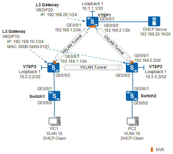
As shown in Figure 1, an enterprise has users located in BD10. VTEP2 and VTEP3 are the gateways for user access and are configured with the same IP address, forming distributed gateways. The DHCP server resides in BD20, and VTEP1 is the gateway and is on a network segment different from that of the users. The DHCP relay function needs to be enabled on distributed gateways for user access to allow users to dynamically obtain IP addresses from the DHCP server using DHCP.
The following configuration solution requires that the DHCP server can parse the Link-selection suboption of Option 82. This solution can implement precise route selection and ensure reply packets of the DHCP server to be forwarded to the correct distributed gateways. For details about this solution, see (Optional) Configuring a Distributed VXLAN Gateway as a DHCP Relay Agent.

This example uses the S6730-H, S6730S-H, S5731-H, S5731S-H, S5731-S, S5731S-S, S5720-HI, S5730-HI, S5732-H, S6730-S, S6730S-S, or S6720-HI as an example to describe the configuration.
Data Preparation
Device |
EVPN Instance |
RD Value |
BD |
VNI |
Router ID |
Peer IP |
|---|---|---|---|---|---|---|
VTEP1 |
evpn20:
|
1:20 |
20 |
20 |
10.1.1.1 |
10.2.2.2; 10.3.3.3 |
VTEP2 |
evpn10:
|
2:10 |
10 |
10 |
10.2.2.2 |
10.1.1.1; 10.3.3.3 |
VTEP3 |
evpn10:
|
3:10 |
10 |
10 |
10.3.3.3 |
10.1.1.1; 10.2.2.2 |
Device |
Interface |
VPN Instance |
VNI |
RD Value |
|---|---|---|---|---|
VTEP1 |
VBDIF 20 |
vpn1:
|
100 |
1:100 |
VTEP2 |
VBDIF 10 |
vpn1:
|
100 |
2:100 |
VTEP3 |
VBDIF 10 |
vpn1:
|
100 |
3:100 |
Configuration Roadmap
The configuration roadmap is as follows:
Configure a VXLAN network.
- Configure a routing protocol on VTEP1, VTEP2, and VTEP3 to ensure Layer 3 interconnection of the network.
- Configure a deployment mode for the VXLAN access service on VTEP1, VTEP2, and VTEP3, and configure a VLAN on Switch1 and Switch2.
- Configure an EVPN instance on VTEP1, VTEP2, and VTEP3, and bind the instance to a BD.
- Configure a VPN instance on VTEP1, VTEP2, and VTEP3, and bind the instance to a VBDIF interface.
- Establish BGP EVPN peer relationships between VTEP1, VTEP2, and VTEP3.
- Configure the destination IP address of the VXLAN tunnel on VTEP1, VTEP2, and VTEP3.
- Configure a VXLAN gateway on VTEP1, VTEP2, and VTEP3.
Configure the DHCP relay function on distributed gateways, including enabling the DHCP relay function, configuring a Loopback interface as the source interface, and configuring the packets to carry the Link-selection suboption.
Add the VXLAN-tunnel-side interfaces to the whitelist for interface attack defense on VTEP2 and VTEP3.
Configure the DHCP server.
Layer 3 interconnection of the campus network is the basis of virtual network construction. If Layer 3 interconnection has been implemented on the live campus network, step 1 in this example can be omitted.
Procedure
- Configure a routing protocol.
# Configure IP addresses for the interfaces on VTEP1. The configurations of VTEP2 and VTEP3 are similar to those of VTEP1, and are not mentioned here. When OSPF is used, the 32-bit loopback interface addresses of devices must be advertised.
<HUAWEI> system-view
[HUAWEI] sysname VTEP1
[VTEP1] interface loopback 1
[VTEP1-LoopBack1] ip address 10.1.1.1 32
[VTEP1-LoopBack1] quit
[VTEP1] interface gigabitethernet 0/0/1
[VTEP1-GigabitEthernet0/0/1] undo portswitch
[VTEP1-GigabitEthernet0/0/1] ip address 192.168.1.2 24
[VTEP1-GigabitEthernet0/0/1] quit
[VTEP1] interface gigabitethernet 0/0/2
[VTEP1-GigabitEthernet0/0/2] undo portswitch
[VTEP1-GigabitEthernet0/0/2] ip address 192.168.2.1 24
[VTEP1-GigabitEthernet0/0/2] quit
[VTEP1] ospf router-id 10.1.1.1
[VTEP1-ospf-1] area 0
[VTEP1-ospf-1-area-0.0.0.0] network 10.1.1.1 0.0.0.0
[VTEP1-ospf-1-area-0.0.0.0] network 192.168.1.0 0.0.0.255
[VTEP1-ospf-1-area-0.0.0.0] network 192.168.2.0 0.0.0.255
[VTEP1-ospf-1-area-0.0.0.0] quit
[VTEP1-ospf-1] quit
# After OSPF is configured, VTEP1, VTEP2, and VTEP3 can learn the loopback interface address of each other and successfully ping each other. The following shows the result when VTEP1 pings VTEP2.
[VTEP1] ping 10.2.2.2 PING 10.2.2.2: 56 data bytes, press CTRL_C to break Reply from 10.2.2.2: bytes=56 Sequence=1 ttl=255 time=240 ms Reply from 10.2.2.2: bytes=56 Sequence=2 ttl=255 time=5 ms Reply from 10.2.2.2: bytes=56 Sequence=3 ttl=255 time=5 ms Reply from 10.2.2.2: bytes=56 Sequence=4 ttl=255 time=14 ms Reply from 10.2.2.2: bytes=56 Sequence=5 ttl=255 time=5 ms --- 10.2.2.2 ping statistics --- 5 packet(s) transmitted 5 packet(s) received 0.00% packet loss round-trip min/avg/max = 5/53/240 ms - Configure VLAN access on Switch1 and Switch2 and configure the access point for the VXLAN service on VTEP1, VTEP2, and VTEP3.
# Configure Switch1.
<HUAWEI> system-view
[HUAWEI] sysname Switch1
[Switch1] vlan 10
[Switch1-vlan10] quit
[Switch1] interface gigabitethernet 0/0/2
[Switch1-GigabitEthernet0/0/2] port link-type access
[Switch1-GigabitEthernet0/0/2] port default vlan 10
[Switch1-GigabitEthernet0/0/2] quit
[Switch1] interface gigabitethernet 0/0/1
[Switch1-GigabitEthernet0/0/1] port link-type trunk
[Switch1-GigabitEthernet0/0/1] port trunk allow-pass vlan 10
[Switch1-GigabitEthernet0/0/1] quit
# Configure Switch2.
<HUAWEI> system-view
[HUAWEI] sysname Switch2
[Switch2] vlan 10
[Switch2-vlan10] quit
[Switch2] interface gigabitethernet 0/0/2
[Switch2-GigabitEthernet0/0/2] port link-type access
[Switch2-GigabitEthernet0/0/2] port default vlan 10
[Switch2-GigabitEthernet0/0/2] quit
[Switch2] interface gigabitethernet 0/0/1
[Switch2-GigabitEthernet0/0/1] port link-type trunk
[Switch2-GigabitEthernet0/0/1] port trunk allow-pass vlan 10
[Switch2-GigabitEthernet0/0/1] quit
# Configure VTEP1.
[VTEP1] vlan 20
[VTEP1-vlan20] quit
[VTEP1] bridge-domain 20
[VTEP1-bd20] l2 binding vlan 20
[VTEP1-bd20] quit
[VTEP1] interface gigabitethernet 0/0/3
[VTEP1-GigabitEthernet0/0/3] port link-type access
[VTEP1-GigabitEthernet0/0/3] port default vlan 20
[VTEP1-GigabitEthernet0/0/3] quit
# Configure VTEP2.
[VTEP2] bridge-domain 10
[VTEP2-bd10] quit
[VTEP2] vcmp role silent
[VTEP2] interface gigabitethernet 0/0/2
[VTEP2-GigabitEthernet0/0/2] port link-type trunk
[VTEP2-GigabitEthernet0/0/2] quit
[VTEP2] interface gigabitethernet 0/0/2.1 mode l2
[VTEP2-GigabitEthernet0/0/2.1] encapsulation dot1q vid 10
[VTEP2-GigabitEthernet0/0/2.1] bridge-domain 10
[VTEP2-GigabitEthernet0/0/2.1] quit
# Configure VTEP3.
[VTEP3] bridge-domain 10
[VTEP3-bd10] quit
[VTEP3] vcmp role silent
[VTEP3] interface gigabitethernet 0/0/2
[VTEP3-GigabitEthernet0/0/2] port link-type trunk
[VTEP3-GigabitEthernet0/0/2] quit
[VTEP3] interface gigabitethernet 0/0/2.1 mode l2
[VTEP3-GigabitEthernet0/0/2.1] encapsulation dot1q vid 10
[VTEP3-GigabitEthernet0/0/2.1] bridge-domain 10
[VTEP3-GigabitEthernet0/0/2.1] quit
- Configure an EVPN instance on VTEP1, VTEP2, and VTEP3, and bind the instance to a BD.
# Configure VTEP1.
[VTEP1] evpn vpn-instance evpn20 bd-mode
[VTEP1-evpn-instance-evpn20] route-distinguisher 1:20
[VTEP1-evpn-instance-evpn20] vpn-target 20:1 both
[VTEP1-evpn-instance-evpn20] vpn-target 1:100 export-extcommunity
[VTEP1-evpn-instance-evpn20] quit
[VTEP1] bridge-domain 20
[VTEP1-bd20] vxlan vni 20
[VTEP1-bd20] evpn binding vpn-instance evpn20
[VTEP1-bd20] quit
# Configure VTEP2.
[VTEP2] evpn vpn-instance evpn10 bd-mode
[VTEP2-evpn-instance-evpn10] route-distinguisher 2:10
[VTEP2-evpn-instance-evpn10] vpn-target 10:1 both
[VTEP2-evpn-instance-evpn10] vpn-target 1:100 export-extcommunity
[VTEP2-evpn-instance-evpn10] quit
[VTEP2] bridge-domain 10
[VTEP2-bd10] vxlan vni 10
[VTEP2-bd10] evpn binding vpn-instance evpn10
[VTEP2-bd10] quit
# Configure VTEP3.
[VTEP3] evpn vpn-instance evpn10 bd-mode
[VTEP3-evpn-instance-evpn10] route-distinguisher 3:10
[VTEP3-evpn-instance-evpn10] vpn-target 10:1 both
[VTEP3-evpn-instance-evpn10] vpn-target 1:100 export-extcommunity
[VTEP3-evpn-instance-evpn10] quit
[VTEP3] bridge-domain 10
[VTEP3-bd10] vxlan vni 10
[VTEP3-bd10] evpn binding vpn-instance evpn10
[VTEP3-bd10] quit
- Configure a BGP EVPN peer relationship among VTEP1, VTEP2, and VTEP3.
# Configure VTEP1.
[VTEP1] ip vpn-instance vpn1
[VTEP1-vpn-instance-vpn1] ipv4-family
[VTEP1-vpn-instance-vpn1-af-ipv4] route-distinguisher 1:100
[VTEP1-vpn-instance-vpn1-af-ipv4] vpn-target 1:100 both evpn
[VTEP1-vpn-instance-vpn1-af-ipv4] quit
[VTEP1-vpn-instance-vpn1] vxlan vni 100
[VTEP1-vpn-instance-vpn1] quit
[VTEP1] interface vbdif 20
[VTEP1-Vbdif20] ip binding vpn-instance vpn1
[VTEP1-Vbdif20] quit
# Configure VTEP2.
[VTEP2] ip vpn-instance vpn1
[VTEP2-vpn-instance-vpn1] ipv4-family
[VTEP2-vpn-instance-vpn1-af-ipv4] route-distinguisher 2:100
[VTEP2-vpn-instance-vpn1-af-ipv4] vpn-target 1:100 both evpn
[VTEP2-vpn-instance-vpn1-af-ipv4] quit
[VTEP2-vpn-instance-vpn1] vxlan vni 100
[VTEP2-vpn-instance-vpn1] quit
[VTEP2] interface vbdif 10
[VTEP2-Vbdif10] ip binding vpn-instance vpn1
[VTEP2-Vbdif10] quit
# Configure VTEP3.
[VTEP3] ip vpn-instance vpn1
[VTEP3-vpn-instance-vpn1] ipv4-family
[VTEP3-vpn-instance-vpn1-af-ipv4] route-distinguisher 3:100
[VTEP3-vpn-instance-vpn1-af-ipv4] vpn-target 1:100 both evpn
[VTEP3-vpn-instance-vpn1-af-ipv4] quit
[VTEP3-vpn-instance-vpn1] vxlan vni 100
[VTEP3-vpn-instance-vpn1] quit
[VTEP3] interface vbdif 10
[VTEP3-Vbdif10] ip binding vpn-instance vpn1
[VTEP3-Vbdif10] quit
- Establish BGP EVPN peer relationships between VTEP1, VTEP2, and VTEP3.
# Configure VTEP1.
[VTEP1] bgp 100
[VTEP1-bgp] router-id 10.1.1.1
[VTEP1-bgp] peer 10.2.2.2 as-number 100
[VTEP1-bgp] peer 10.2.2.2 connect-interface LoopBack1
[VTEP1-bgp] peer 10.3.3.3 as-number 100
[VTEP1-bgp] peer 10.3.3.3 connect-interface LoopBack1
[VTEP1-bgp] l2vpn-family evpn
[VTEP1-bgp-af-evpn] peer 10.2.2.2 enable
[VTEP1-bgp-af-evpn] peer 10.2.2.2 advertise irb
[VTEP1-bgp-af-evpn] peer 10.3.3.3 enable
[VTEP1-bgp-af-evpn] peer 10.3.3.3 advertise irb
[VTEP1-bgp-af-evpn] quit
[VTEP1-bgp] ipv4-family vpn-instance vpn1
[VTEP1-bgp-vpn1] advertise l2vpn evpn
[VTEP1-bgp-vpn1] import-route direct
[VTEP1-bgp-vpn1] quit
[VTEP1-bgp] quit
# Configure VTEP2.
[VTEP2] bgp 100
[VTEP2-bgp] router-id 10.2.2.2
[VTEP2-bgp] peer 10.1.1.1 as-number 100
[VTEP2-bgp] peer 10.1.1.1 connect-interface LoopBack1
[VTEP2-bgp] peer 10.3.3.3 as-number 100
[VTEP2-bgp] peer 10.3.3.3 connect-interface LoopBack1
[VTEP2-bgp] l2vpn-family evpn
[VTEP2-bgp-af-evpn] peer 10.1.1.1 enable
[VTEP2-bgp-af-evpn] peer 10.1.1.1 advertise irb
[VTEP2-bgp-af-evpn] peer 10.3.3.3 enable
[VTEP2-bgp-af-evpn] peer 10.3.3.3 advertise irb
[VTEP2-bgp-af-evpn] quit
[VTEP2-bgp] ipv4-family vpn-instance vpn1
[VTEP2-bgp-vpn1] advertise l2vpn evpn
[VTEP2-bgp-vpn1] import-route direct
[VTEP2-bgp-vpn1] quit
[VTEP2-bgp] quit
# Configure VTEP3.
[VTEP3] bgp 100
[VTEP3-bgp] router-id 10.3.3.3
[VTEP3-bgp] peer 10.1.1.1 as-number 100
[VTEP3-bgp] peer 10.1.1.1 connect-interface LoopBack1
[VTEP3-bgp] peer 10.2.2.2 as-number 100
[VTEP3-bgp] peer 10.2.2.2 connect-interface LoopBack1
[VTEP3-bgp] l2vpn-family evpn
[VTEP3-bgp-af-evpn] peer 10.1.1.1 enable
[VTEP3-bgp-af-evpn] peer 10.1.1.1 advertise irb
[VTEP3-bgp-af-evpn] peer 10.2.2.2 enable
[VTEP3-bgp-af-evpn] peer 10.2.2.2 advertise irb
[VTEP3-bgp-af-evpn] quit
[VTEP3-bgp] ipv4-family vpn-instance vpn1
[VTEP3-bgp-vpn1] advertise l2vpn evpn
[VTEP3-bgp-vpn1] import-route direct
[VTEP3-bgp-vpn1] quit
[VTEP3-bgp] quit
- Configure the destination IP address of the VXLAN tunnel on VTEP1, VTEP2, and VTEP3.
# Configure VTEP1.
[VTEP1] interface nve 1
[VTEP1-Nve1] source 10.1.1.1
[VTEP1-Nve1] vni 20 head-end peer-list protocol bgp
[VTEP1-Nve1] quit
# Configure VTEP2.
[VTEP2] interface nve 1
[VTEP2-Nve1] source 10.2.2.2
[VTEP2-Nve1] vni 10 head-end peer-list protocol bgp
[VTEP2-Nve1] quit
# Configure VTEP3.
[VTEP3] interface nve 1
[VTEP3-Nve1] source 10.3.3.3
[VTEP3-Nve1] vni 10 head-end peer-list protocol bgp
[VTEP3-Nve1] quit
- Configure a distributed gateway on VTEP2 and VTEP3, and configure a common VXLAN gateway on VTEP1.
# Configure VTEP1.
[VTEP1] interface vbdif 20
[VTEP1-Vbdif20] ip address 192.168.20.1 24
[VTEP1-Vbdif20] quit
# Configure VTEP2.
[VTEP2] interface vbdif 10
[VTEP2-Vbdif10] ip address 192.168.10.1 24
[VTEP2-Vbdif10] arp distribute-gateway enable
[VTEP2-Vbdif10] arp collect host enable
[VTEP2-Vbdif10] mac-address 0000-5e00-0101
[VTEP2-Vbdif10] quit
# Configure VTEP3.
[VTEP3] interface vbdif 10
[VTEP3-Vbdif10] ip address 192.168.10.1 24
[VTEP3-Vbdif10] arp distribute-gateway enable
[VTEP3-Vbdif10] arp collect host enable
[VTEP3-Vbdif10] mac-address 0000-5e00-0101
[VTEP3-Vbdif10] quit
- Verify VXLAN configuration results.
# After the preceding configuration, run the display vxlan tunnel command on VTEP1, VTEP2, and VTEP3. You can view that VXLAN tunnel information is displayed. The following shows the result on VTEP1.
[VTEP1] display vxlan tunnel
 Tunnel ID       Source              Destination         State     Type
 ----------------------------------------------------------------------------
 11              10.1.1.1            10.2.2.2            up        l3 dynamic
 13              10.1.1.1            10.3.3.3            up        l3 dynamic
 ----------------------------------------------------------------------------
 Number of vxlan tunnel :
 Total : 2    Static: 0    L2 dynamic: 0    L3 dynamic: 2
- Configure the DHCP relay function on the distributed gateways VTEP2 and VTEP3.
# Configure VTEP2.
[VTEP2] interface LoopBack 2
[VTEP2-LoopBack2] ip binding vpn-instance vpn1
[VTEP2-LoopBack2] ip address 10.21.1.1 255.255.255.255
[VTEP2-LoopBack2] quit
[VTEP2] dhcp enable
[VTEP2] interface vbdif 10
[VTEP2-Vbdif10] dhcp select relay
[VTEP2-Vbdif10] dhcp relay server-ip 192.168.20.10
[VTEP2-Vbdif10] dhcp relay giaddr source-interface loopback 2
[VTEP2-Vbdif10] dhcp relay information link-selection insert enable
[VTEP2-Vbdif10] quit
# Configure VTEP3.
[VTEP3] interface LoopBack 2
[VTEP3-LoopBack2] ip binding vpn-instance vpn1
[VTEP3-LoopBack2] ip address 10.22.1.1 255.255.255.255
[VTEP3-LoopBack2] quit
[VTEP3] dhcp enable
[VTEP3] interface vbdif 10
[VTEP3-Vbdif10] dhcp select relay
[VTEP3-Vbdif10] dhcp relay server-ip 192.168.20.10
[VTEP3-Vbdif10] dhcp relay giaddr source-interface loopback 2
[VTEP3-Vbdif10] dhcp relay information link-selection insert enable
[VTEP3-Vbdif10] quit
- Verify the DHCP Relay configuration.
# After the preceding configuration, run the display dhcp relay command on VTEP2 and VTEP3. You can view the DHCP relay configuration on the interfaces. The following shows the result on VTEP2.
[VTEP2] display dhcp relay interface vbdif 10
 DHCP relay agent running information of interface Vbdif10 :
 Server IP address [00] : 192.168.20.10
 Gateway address in use : 192.168.10.1
- Configure the DHCP server.The configuration details are not provided here. The configurations required for the DHCP server are as follows:
- An address pool is configured on the DHCP server so that the DHCP server assigns IP addresses to DHCP clients.
- An address lease is configured to improve IP address usage efficiency.
Configuration Files
Configuration file of VTEP1
#
sysname VTEP1
#
vlan batch 20
#
ip vpn-instance vpn1
 ipv4-family
  route-distinguisher 1:100
  vpn-target 1:100 export-extcommunity evpn
  vpn-target 1:100 import-extcommunity evpn
 vxlan vni 100
#
evpn vpn-instance evpn20 bd-mode
 route-distinguisher 1:20
 vpn-target 1:100 20:1 export-extcommunity
 vpn-target 20:1 import-extcommunity
#
bridge-domain 20
 l2 binding vlan 20
 vxlan vni 20
 evpn binding vpn-instance evpn20
#
interface GigabitEthernet0/0/1
 undo portswitch
 ip address 192.168.1.2 255.255.255.0
#
interface GigabitEthernet0/0/2
 undo portswitch
 ip address 192.168.2.1 255.255.255.0
#
interface GigabitEthernet0/0/3
 port link-type access
 port default vlan 20
#
interface LoopBack1
 ip address 10.1.1.1 255.255.255.255
#
interface Vbdif20
 ip binding vpn-instance vpn1
 ip address 192.168.20.1 255.255.255.0
#
interface Nve1
 source 10.1.1.1
 vni 20 head-end peer-list protocol bgp
#
bgp 100
 router-id 10.1.1.1
 peer 10.2.2.2 as-number 100
 peer 10.2.2.2 connect-interface LoopBack1
 peer 10.3.3.3 as-number 100
 peer 10.3.3.3 connect-interface LoopBack1
 #
 ipv4-family unicast
  undo synchronization
  peer 10.2.2.2 enable
  peer 10.3.3.3 enable
 #
 l2vpn-family evpn
  policy vpn-target
  peer 10.2.2.2 enable
  peer 10.2.2.2 advertise irb
  peer 10.3.3.3 enable
  peer 10.3.3.3 advertise irb
 #
 ipv4-family vpn-instance vpn1
  import-route direct
  advertise l2vpn evpn
#
ospf 1 router-id 10.1.1.1
 area 0.0.0.0
  network 10.1.1.1 0.0.0.0
  network 192.168.1.0 0.0.0.255
  network 192.168.2.0 0.0.0.255
#
return
VTEP2 configuration file
#
sysname VTEP2
#
vcmp role silent
#
dhcp enable
#
ip vpn-instance vpn1
 ipv4-family
  route-distinguisher 2:100
  vpn-target 1:100 export-extcommunity evpn
  vpn-target 1:100 import-extcommunity evpn
 vxlan vni 100
#
evpn vpn-instance evpn10 bd-mode
 route-distinguisher 2:10
 vpn-target 1:100 10:1 export-extcommunity
 vpn-target 10:1 import-extcommunity
#
bridge-domain 10
 vxlan vni 10
 evpn binding vpn-instance evpn10
#
interface GigabitEthernet0/0/1
 undo portswitch
 ip address 192.168.1.1 255.255.255.0
#
interface GigabitEthernet0/0/2
 port link-type trunk
#
interface GigabitEthernet0/0/2.1 mode l2
 encapsulation dot1q vid 10
 bridge-domain 10
#
interface LoopBack1
 ip address 10.2.2.2 255.255.255.255
#
interface LoopBack2
 ip binding vpn-instance vpn1
 ip address 10.21.1.1 255.255.255.255
#
interface Vbdif10
 mac-address 0000-5e00-0101
 ip binding vpn-instance vpn1
 arp collect host enable
 arp distribute-gateway enable
 ip address 192.168.10.1 255.255.255.0
 dhcp select relay
 dhcp relay server-ip 192.168.20.10
 dhcp relay giaddr source-interface LoopBack2
 dhcp relay information link-selection insert enable
#
interface Nve1
 source 10.2.2.2
 vni 10 head-end peer-list protocol bgp
#
bgp 100
 router-id 10.2.2.2
 peer 10.1.1.1 as-number 100
 peer 10.1.1.1 connect-interface LoopBack1
 peer 10.3.3.3 as-number 100
 peer 10.3.3.3 connect-interface LoopBack1
 #
 ipv4-family unicast
  undo synchronization
  peer 10.1.1.1 enable
  peer 10.3.3.3 enable
 #
 l2vpn-family evpn
  policy vpn-target
  peer 10.1.1.1 enable
  peer 10.1.1.1 advertise irb
  peer 10.3.3.3 enable
  peer 10.3.3.3 advertise irb
 #
 ipv4-family vpn-instance vpn1
  import-route direct
  advertise l2vpn evpn
#
ospf 1 router-id 10.2.2.2
 area 0.0.0.0
  network 10.2.2.2 0.0.0.0
  network 192.168.1.0 0.0.0.255
#
return
VTEP3 configuration file
#
sysname VTEP3
#
vcmp role silent
#
dhcp enable
#
ip vpn-instance vpn1
 ipv4-family
  route-distinguisher 3:100
  vpn-target 1:100 export-extcommunity evpn
  vpn-target 1:100 import-extcommunity evpn
 vxlan vni 100
#
evpn vpn-instance evpn10 bd-mode
 route-distinguisher 3:10
 vpn-target 1:100 10:1 export-extcommunity
 vpn-target 10:1 import-extcommunity
#
bridge-domain 10
 vxlan vni 10
 evpn binding vpn-instance evpn10
#
interface GigabitEthernet0/0/1
 undo portswitch
 ip address 192.168.2.2 255.255.255.0
#
interface GigabitEthernet0/0/2
 port link-type trunk
#
interface GigabitEthernet0/0/2.1 mode l2
 encapsulation dot1q vid 10
 bridge-domain 10
#
interface LoopBack1
 ip address 10.3.3.3 255.255.255.255
#
interface LoopBack2
 ip binding vpn-instance vpn1
 ip address 10.22.1.1 255.255.255.255
#
interface Vbdif10
 mac-address 0000-5e00-0101
 ip binding vpn-instance vpn1
 arp collect host enable
 arp distribute-gateway enable
 ip address 192.168.10.1 255.255.255.0
 dhcp select relay
 dhcp relay server-ip 192.168.20.10
 dhcp relay giaddr source-interface LoopBack2
 dhcp relay information link-selection insert enable
#
interface Nve1
 source 10.3.3.3
 vni 10 head-end peer-list protocol bgp
#
bgp 100
 router-id 10.3.3.3
 peer 10.1.1.1 as-number 100
 peer 10.1.1.1 connect-interface LoopBack1
 peer 10.2.2.2 as-number 100
 peer 10.2.2.2 connect-interface LoopBack1
 #
 ipv4-family unicast
  undo synchronization
  peer 10.1.1.1 enable
  peer 10.2.2.2 enable
 #
 l2vpn-family evpn
  policy vpn-target
  peer 10.1.1.1 enable
  peer 10.1.1.1 advertise irb
  peer 10.2.2.2 enable
  peer 10.2.2.2 advertise irb
 #
 ipv4-family vpn-instance vpn1
  import-route direct
  advertise l2vpn evpn
#
ospf 1 router-id 10.3.3.3
 area 0.0.0.0
  network 10.3.3.3 0.0.0.0
  network 192.168.2.0 0.0.0.255
#
return
Configuration file of Switch1
#
sysname Switch1
#
vlan 10
#
interface GigabitEthernet0/0/1
 port link-type trunk
 port trunk allow-pass vlan 10
#
interface GigabitEthernet0/0/2
 port link-type access
 port default vlan 10
#
return
Configuration file of Switch2
#
sysname Switch2
#
vlan 10
#
interface GigabitEthernet0/0/1
 port link-type trunk
 port trunk allow-pass vlan 10
#
interface GigabitEthernet0/0/2
 port link-type access
 port default vlan 10
#
return