Example for Configuring Layer 2 Roaming Between ACs in Distributed VXLAN Gateway Networking
Networking Requirements
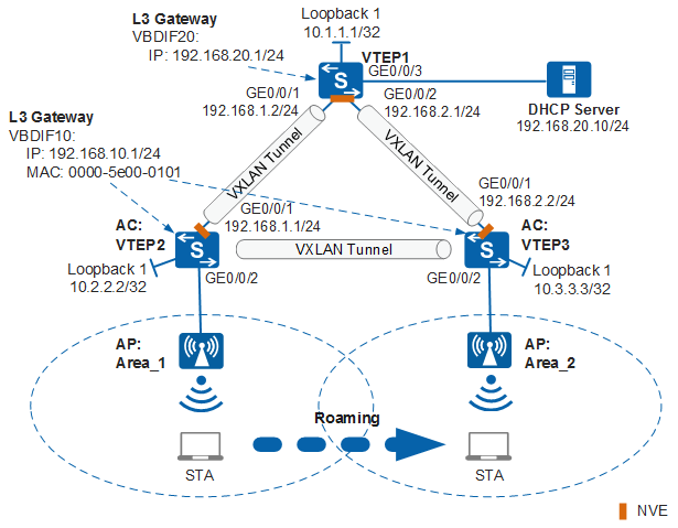
An enterprise deploys ACs in different areas. The distributed VXLAN gateway and DHCP relay functions are configured on the ACs. Wireless users access the network through the APs connected to the ACs. The DHCP server assigns IP addresses. The enterprise requires Layer 2 roaming of wireless users between the ACs.
On the network in Figure 1, a STA needs to roam between Area_1 and Area_2.

The switches in this example can only be S6730-H, S6730S-H, S5731-H, S5720-HI, S5730-HI, or S6720-HI switches.
Data Preparation
Device |
EVPN Instance |
RD Value |
BD |
VNI |
Router ID |
Peer IP |
|---|---|---|---|---|---|---|
VTEP1 |
evpn20:
|
1:20 |
20 |
20 |
10.1.1.1 |
10.2.2.2; 10.3.3.3 |
VTEP2 |
evpn10:
|
2:10 |
10 |
10 |
10.2.2.2 |
10.1.1.1; 10.3.3.3 |
VTEP3 |
evpn10:
|
3:10 |
10 |
10 |
10.3.3.3 |
10.1.1.1; 10.2.2.2 |
Device |
Interface |
VPN Instance |
VNI |
RD Value |
|---|---|---|---|---|
VTEP1 |
VBDIF 20 |
vpn1:
|
100 |
1:100 |
VTEP2 |
VBDIF 10 |
vpn1:
|
100 |
2:100 |
VTEP3 |
VBDIF 10 |
vpn1:
|
100 |
3:100 |
Configuration Item |
VTEP2 |
VTEP3 |
|---|---|---|
IP address pool for APs |
On VTEP2, configure a DHCP server based on VLANIF 100 to assign IP addresses to the connected AP. |
On VTEP3, configure a DHCP server based on VLANIF 200 to assign IP addresses to the connected AP. |
IP address pool for APs |
192.168.100.2 to 192.168.100.254/24 |
192.168.200.2 to 192.168.200.254/24 |
IP address pool for STAs |
192.168.10.2 to 192.168.10.254/24 |
192.168.10.2 to 192.168.10.254/24 |
AC's source interface IP address |
Source interface: VLANIF100: 192.168.100.1/24 |
Source interface: VLANIF200: 192.168.200.1/24 |
AP group |
|
|
Regulatory domain profile |
|
|
SSID profile |
|
|
Security profile |
|
|
VAP profile |
|
|
Roaming parameters |
|
|
Configuration Roadmap
The configuration roadmap is as follows:
- Configure a VXLAN network.
- Configure a routing protocol on VTEP1, VTEP2, and VTEP3 to ensure Layer 3 interconnection.
- Configure a deployment mode for the VXLAN access service on VTEP1, VTEP2, and VTEP3.
- Configure an EVPN instance on VTEP1, VTEP2, and VTEP3, and bind the instance to a bridge domain (BD).
- Configure a VPN instance on VTEP1, VTEP2, and VTEP3, and bind the instance to a VBDIF.
- Configure a BGP EVPN peer relationship among VTEP1, VTEP2, and VTEP3.
- Configure the destination IP address of the VXLAN tunnel on VTEP1, VTEP2, and VTEP3.
- Configure a VXLAN gateway on VTEP1, VTEP2, and VTEP3.
Add the VXLAN tunnel-side interfaces to the whitelist for port attack defense on VTEP2 and VTEP3.
Configure VTEP2 and VTEP3 to allow the management VLANs of the APs and configure the DHCP server function to assign management IP addresses to the APs.
Configure routing protocols on VTEP2 and VTEP3 to implement communication between the source IP addresses of CAPWAP tunnels.
Configure WLAN service parameters on VTEP2 and VTEP3 for STAs to access the WLAN.
Configure WLAN roaming on VTEP2 and VTEP3 to implement Layer 2 roaming between ACs.
Layer 3 interconnection of the campus network is the basis of the virtual network. If Layer 3 interconnection has been implemented on the live campus network, step 1 in this example can be omitted.
Configuration Precautions
- ACs in the same mobility group must run the same system software of the C version. Otherwise, inter-AC roaming may fail.
- The mobility group name and IP address for establishing an inter-AC tunnel must be configured on each AC in the mobility group. ACs must be added to the mobility group.
- The IP addresses used for establishing an inter-AC tunnel between ACs in a mobility group must be the CAPWAP source IP addresses of the ACs. When multiple CAPWAP source IP addresses are configured, only on CAPWAP source IP address can be used to establish an inter-AC tunnel.
- The mobility group name must be the same on each AC.
Procedure
- Configure a VXLAN network.
- Configure the DHCP relay function on VTEP2 and VTEP3 and the re-routing function for the DHCP relay agents on the distributed gateways.
# Configure VTEP2.
[VTEP2] dhcp enable
[VTEP2] dhcp option82 vendor-specific format vendor-sub-option 2 ip-address 10.2.2.2
[VTEP2] bridge-domain 10
[VTEP2-bd10] dhcp option82 insert enable
[VTEP2-bd10] dhcp option82 encapsulation vendor-specific-id
[VTEP2-bd10] quit
[VTEP2] interface vbdif 10
[VTEP2-Vbdif10] dhcp select relay
[VTEP2-Vbdif10] dhcp relay server-ip 192.168.20.10
[VTEP2-Vbdif10] dhcp relay information enable
[VTEP2-Vbdif10] dhcp relay anycast gateway re-route enable
[VTEP2-Vbdif10] quit
# Configure VTEP3.
[VTEP3] dhcp enable
[VTEP3] dhcp option82 vendor-specific format vendor-sub-option 2 ip-address 10.3.3.3
[VTEP3] bridge-domain 10
[VTEP3-bd10] dhcp option82 insert enable
[VTEP3-bd10] dhcp option82 encapsulation vendor-specific-id
[VTEP3-bd10] quit
[VTEP3] interface vbdif 10
[VTEP3-Vbdif10] dhcp select relay
[VTEP3-Vbdif10] dhcp relay server-ip 192.168.20.10
[VTEP3-Vbdif10] dhcp relay information enable
[VTEP3-Vbdif10] dhcp relay anycast gateway re-route enable
[VTEP3-Vbdif10] quit
- Add the VXLAN tunnel-side interfaces to the whitelist for port attack defense on VTEP2 and VTEP3.
# Add the VXLAN tunnel-side interface GigabitEthernet0//0/1 to the whitelist for port attack defense on VTEP2.
[VTEP2] cpu-defend policy vxlan_tunnel_side
[VTEP2-cpu-defend-policy-vxlan_tunnel_side] auto-port-defend whitelist 1 interface GigabitEthernet0/0/1
[VTEP2-cpu-defend-policy-vxlan_tunnel_side] quit
[VTEP2] cpu-defend-policy vxlan_tunnel_side global
# Add the VXLAN tunnel-side interface GigabitEthernet0//0/1 to the whitelist for port attack defense on VTEP3.
[VTEP3] cpu-defend policy vxlan_tunnel_side
[VTEP3-cpu-defend-policy-vxlan_tunnel_side] auto-port-defend whitelist 1 interface GigabitEthernet0/0/1
[VTEP3-cpu-defend-policy-vxlan_tunnel_side] quit
[VTEP3] cpu-defend-policy vxlan_tunnel_side global
- Verify the DHCP Relay configuration.
# After the preceding configuration, run the display dhcp relay command on VTEP2 and VTEP3. You can view the DHCP relay configuration on the interfaces. The following shows the result on VTEP2.
[VTEP2] display dhcp relay interface vbdif 10
 DHCP relay agent running information of interface Vbdif10 :
 Server IP address [00] : 192.168.20.10
 Gateway address in use : 192.168.10.1
- Configure the DHCP server.The configuration details are not provided here. The configurations required for the DHCP server are as follows:
- An address pool is configured on the DHCP server so that the DHCP server assigns IP addresses to DHCP clients.
- An address lease is configured to improve IP address usage efficiency.
- Configure VTEP2 and VTEP3 to allow the management VLANs of the APs and configure the DHCP server function to assign management IP addresses to the APs.
# Configure VTEP2.
[VTEP2] vlan 100
[VTEP22-vlan100] quit
[VTEP2] interface gigabitethernet 0/0/2
[VTEP2-GigabitEthernet0/0/2] port link-type access
[VTEP2-GigabitEthernet0/0/2] port default vlan 100
[VTEP2-GigabitEthernet0/0/2] quit
[VTEP2] interface vlanif 100
[VTEP2-Vlanif100] ip address 192.168.100.1 24
[VTEP2-Vlanif100] dhcp select interface
[VTEP2-Vlanif100] quit
# Configure VTEP3.
[VTEP3] vlan 200
[VTEP3-vlan200] quit
[VTEP3] interface gigabitethernet 0/0/2
[VTEP3-GigabitEthernet0/0/2] port link-type access
[VTEP3-GigabitEthernet0/0/2] port default vlan 200
[VTEP3-GigabitEthernet0/0/2] quit
[VTEP3] interface vlanif 200
[VTEP3-Vlanif200] ip address 192.168.200.1 24
[VTEP3-Vlanif200] dhcp select interface
[VTEP3-Vlanif200] quit
- Configure the source IP addresses of CAPWAP tunnels on VTEP2 and VTEP3 functioning as the ACs.
# Configure VTEP2.
[VTEP2] capwap source interface vlanif 100
# Configure VTEP3.
[VTEP3] capwap source interface vlanif 200
- Configure routing protocols on VTEP2 and VTEP3 to implement communication between the source IP addresses of CAPWAP tunnels.
# Configure VTEP2.
[VTEP2] ospf
[VTEP2-ospf-1] area 0
[VTEP2-ospf-1-area-0.0.0.0] network 192.168.100.0 0.0.0.255
[VTEP2-ospf-1-area-0.0.0.0] quit
[VTEP2-ospf-1] quit
# Configure VTEP3.
[VTEP3] ospf
[VTEP3-ospf-1] area 0
[VTEP3-ospf-1-area-0.0.0.0] network 192.168.200.0 0.0.0.255
[VTEP3-ospf-1-area-0.0.0.0] quit
[VTEP3-ospf-1] quit
- Configure APs to go online on VTEP2 and VTEP3. The following uses VTEP2 as an example. The configuration of VTEP3 is similar to that of VTEP2.# Create an AP group to which APs with the same configuration are to be added.
[VTEP2] wlan
[VTEP2-wlan-view] ap-group name ap-group1
[VTEP2-wlan-ap-group-ap-group1] quit
# Create a regulatory domain profile, configure the country code for AC in the profile, and bind the profile to the AP group.[VTEP2-wlan-view] regulatory-domain-profile name default [VTEP2-wlan-regulate-domain-default] country-code cn [VTEP2-wlan-regulate-domain-default] quit [VTEP2-wlan-view] ap-group name ap-group1 [VTEP2-wlan-ap-group-ap-group1] regulatory-domain-profile default Warning: Modifying the country code will clear channel, power and antenna gain configurations of the radio and reset the AP. Continue?[Y/N]:y [VTEP2-wlan-ap-group-ap-group1] quit [VTEP2-wlan-view] quit
# Import an AP offline on AC and add the AP to the AP group ap-group1. Assume that the AP's MAC address is 60de-4476-e360. Configure a name for the AP based on the AP's deployment location, so that you will know where the AP is deployed from its name. If the AP with MAC address 60de-4476-e360 is in area 1, name the AP area_1. The default AP authentication mode is MAC address authentication. If the default settings are retained, you do not need to run the ap auth-mode mac-auth command.
In this example, the AP5030DN is used and has two radios: radio 0 (2.4 GHz radio) and radio 1 (5 GHz radio).
[VTEP2] wlan
[VTEP2-wlan-view] ap auth-mode mac-auth
[VTEP2-wlan-view] ap-id 0 ap-mac 60de-4476-e360
[VTEP2-wlan-ap-0] ap-name area_1
Warning: This operation may cause AP reset. Continue? [Y/N]:y
[VTEP2-wlan-ap-0] ap-group ap-group1
Warning: This operation may cause AP reset. If the country code changes, it will clear channel, power and antenna gain configuration s of the radio, Whether to continue? [Y/N]:y
[VTEP2-wlan-ap-0] quit
# After the AP is powered on, run the display ap all command to check the AP state. If the State field displays nor, the AP has gone online.[VTEP2-wlan-view] display ap all Total AP information: nor : normal [1] Extra information: P : insufficient power supply -------------------------------------------------------------------------------------------------- ID MAC Name Group IP Type State STA Uptime ExtraInfo -------------------------------------------------------------------------------------------------- 0 60de-4476-e360 area_1 ap-group1 10.23.100.254 AP5030DN nor 0 10S - -------------------------------------------------------------------------------------------------- Total: 1
- Configure WLAN service parameters on VTEP2 and VTEP3. The following uses VTEP2 as an example. The configuration of VTEP3 is similar to that of VTEP2.# Create security profile wlan-net and configure a security policy in the profile.
The following example sets the security policy to WPA-WPA2+PSK+AES and password to a1234567. In actual situations, configure the security policy based on service requirements.
[VTEP2-wlan-view] security-profile name wlan-net
[VTEP2-wlan-sec-prof-wlan-net] security wpa-wpa2 psk pass-phrase a1234567 aes
[VTEP2-wlan-sec-prof-wlan-net] quit
# Create SSID profile wlan-net and set the SSID name to wlan-net.[VTEP2-wlan-view] ssid-profile name wlan-net [VTEP2-wlan-ssid-prof-wlan-net] ssid wlan-net [VTEP2-wlan-ssid-prof-wlan-net] quit
# Create VAP profile wlan-net, set the data forwarding mode and service VLAN, and bind the security profile and SSID profile to the VAP profile.[VTEP2-wlan-view] vap-profile name wlan-net [VTEP2-wlan-vap-prof-wlan-net] forward-mode tunnel [VTEP2-wlan-vap-prof-wlan-net] service-vlan vlan-id 10 [VTEP2-wlan-vap-prof-wlan-net] security-profile wlan-net [VTEP2-wlan-vap-prof-wlan-net] ssid-profile wlan-net [VTEP2-wlan-vap-prof-wlan-net] quit
# Bind the VAP profile to the AP group, and apply configurations of VAP profile wlan-net to radios 0 and 1 of the AP.[VTEP2-wlan-view] ap-group name ap-group1 [VTEP2-wlan-ap-group-ap-group1] vap-profile wlan-net wlan 1 radio 0 [VTEP2-wlan-ap-group-ap-group1] vap-profile wlan-net wlan 1 radio 1 [VTEP2-wlan-ap-group-ap-group1] quit
- Configure WLAN roaming on VTEP2 and VTEP3.
Configure IP addresses for establishing an inter-AC tunnel.
# Configure VTEP2.
[VTEP2-wlan-view] mobility-server local ip-address 192.168.100.1
# Configure VTEP3.
[VTEP3-wlan-view] mobility-server local ip-address 192.168.200.1
Create a mobility group, and add VTEP2 and VTEP3 to the mobility group.
# Configure VTEP2.
[VTEP2-wlan-view] mobility-group name mobility
[VTEP2-mc-mg-mobility] member ip-address 192.168.100.1
[VTEP2-mc-mg-mobility] member ip-address 192.168.200.1
[VTEP2-mc-mg-mobility] quit
# Configure VTEP3.
[VTEP3-wlan-view] mobility-group name mobility
[VTEP3-mc-mg-mobility] member ip-address 192.168.100.1
[VTEP3-mc-mg-mobility] member ip-address 192.168.200.1
[VTEP3-mc-mg-mobility] quit
- Verify the configuration.# The ACs automatically deliver WLAN service configurations to the APs. After the configuration is complete, run the display vap ssid wlan-net command on VTEP2 and VTEP3 to check VAP information. If Status in the command output displays ON, the VAPs have been successfully created on AP radios.
[VTEP2-wlan-view] display vap ssid wlan-net
WID : WLAN ID
--------------------------------------------------------------------------------------
AP ID AP name        RfID WID  BSSID          Status  Auth type         STA    SSID
--------------------------------------------------------------------------------------
0     area_1         0    1    60DE-4476-E360 ON      WPA/WPA2-PSK      0      wlan-net
0     area_1         1    1    60DE-4476-E370 ON      WPA/WPA2-PSK      0      wlan-net
---------------------------------------------------------------------------------------
Total: 2
[VTEP3-wlan-view] display vap ssid wlan-net
WID : WLAN ID
--------------------------------------------------------------------------------------
AP ID AP name        RfID WID  BSSID          Status  Auth type         STA  SSID
--------------------------------------------------------------------------------------
1     area_2         0    1    DCD2-FC04-B500 ON      WPA/WPA2-PSK       0    wlan-net
1     area_2         1    1    DCD2-FC04-B510 ON      WPA/WPA2-PSK       0    wlan-net
-------------------------------------------------------------------------------------
Total: 2
Run the display mobility-group name mobility command on VTEP2 to check working states of VTEP2 and VTEP3. If State displays normal, VTEP2 and VTEP3 work properly.
# In the coverage area of AP_1, connect a STA to the WLAN with SSID wlan-net and enter the password a1234567. After the STA successfully associates with the WLAN, run the display station ssid wlan-net command on VTEP2 to check STA information. The command output shows that the STA with MAC address e019-1dc7-1e08 is associated with area_1.[VTEP2-wlan-view] display station ssid wlan-net Rf/WLAN: Radio ID/WLAN ID Rx/Tx: link receive rate/link transmit rate(Mbps) ------------------------------------------------------------------------------------ STA MAC AP ID Ap name Rf/WLAN Band Type Rx/Tx RSSI VLAN IP address ------------------------------------------------------------------------------------ e019-1dc7-1e08 0 area_1 1/1 5G 11n 46/59 -57 101 192.168.10.161 ------------------------------------------------------------------------------------ Total: 1 2.4G: 0 5G: 1
# After the STA moves from the coverage area of area_1 to that of area_2, run the display station ssid wlan-net command on AC_2 to check the STA's access information. The command output shows that the STA is associated with area_2.[VTEP3-wlan-view] display station ssid wlan-net Rf/WLAN: Radio ID/WLAN ID Rx/Tx: link receive rate/link transmit rate(Mbps) ------------------------------------------------------------------------------------ STA MAC AP ID Ap name Rf/WLAN Band Type Rx/Tx RSSI VLAN IP address ------------------------------------------------------------------------------------ e019-1dc7-1e08 1 area_2 1/1 5G 11n 46/59 -58 101 192.168.10.161 ------------------------------------------------------------------------------------ Total: 1 2.4G: 0 5G: 1
# Run the display station roam-track sta-mac e019-1dc7-1e08 command on VTEP3 to check the STA roaming track.[VTEP3-wlan-view] display station roam-track sta-mac e019-1dc7-1e08 Access SSID:wlan-net Rx/Tx: link receive rate/link transmit rate(Mbps) c:PMK Cache Roam r:802.11r Roam s:Same Frequency Network ------------------------------------------------------------------------------ L2/L3 AC IP AP name Radio ID BSSID TIME In/Out RSSI Out Rx/Tx ------------------------------------------------------------------------------ -- 192.168.100.1 area_1 1 60de-4476-e360 2018/06/09 16:11:51 -57/-57 22/3 L2 192.168.200.1 area_2 1 dcd2-fc04-b500 2018/06/09 16:13:53 -58/- -/- ------------------------------------------------------------------------------ Number: 1
Configuration Files
-
#
sysname VTEP1
#
vlan batch 20
#
ip vpn-instance vpn1
 ipv4-family
  route-distinguisher 1:100
  vpn-target 1:100 export-extcommunity evpn
  vpn-target 1:100 import-extcommunity evpn
 vxlan vni 100
#
evpn vpn-instance evpn20 bd-mode
 route-distinguisher 1:20
 vpn-target 1:100 20:1 export-extcommunity
 vpn-target 20:1 import-extcommunity
#
bridge-domain 20
 l2 binding vlan 20
 vxlan vni 20
 evpn binding vpn-instance evpn20
#
interface GigabitEthernet0/0/1
 undo portswitch
 ip address 192.168.1.2 255.255.255.0
#
interface GigabitEthernet0/0/2
 undo portswitch
 ip address 192.168.2.1 255.255.255.0
#
interface GigabitEthernet0/0/3
 port link-type access
 port default vlan 20
#
interface LoopBack1
 ip address 10.1.1.1 255.255.255.255
#
interface Vbdif20
 ip binding vpn-instance vpn1
 ip address 192.168.20.1 255.255.255.0
#
interface Nve1
 source 10.1.1.1
 vni 20 head-end peer-list protocol bgp
#
bgp 100
 router-id 10.1.1.1
 peer 10.2.2.2 as-number 100
 peer 10.2.2.2 connect-interface LoopBack1
 peer 10.3.3.3 as-number 100
 peer 10.3.3.3 connect-interface LoopBack1
 #
 ipv4-family unicast
  undo synchronization
  peer 10.2.2.2 enable
  peer 10.3.3.3 enable
 #
 l2vpn-family evpn
  policy vpn-target
  peer 10.2.2.2 enable
  peer 10.2.2.2 advertise irb
  peer 10.3.3.3 enable
  peer 10.3.3.3 advertise irb
 #
 ipv4-family vpn-instance vpn1
  import-route direct
  advertise l2vpn evpn
#
ospf 1 router-id 10.1.1.1
 area 0.0.0.0
  network 10.1.1.1 0.0.0.0
  network 192.168.1.0 0.0.0.255
  network 192.168.2.0 0.0.0.255
#
return
-
#
sysname VTEP2
#
dhcp enable
#
dhcp option82 vendor-specific format vendor-sub-option 2 ip-address 10.2.2.2
#
ip vpn-instance vpn1
 ipv4-family
  route-distinguisher 2:100
  vpn-target 1:100 export-extcommunity evpn
  vpn-target 1:100 import-extcommunity evpn
 vxlan vni 100
#
evpn vpn-instance evpn10 bd-mode
 route-distinguisher 2:10
 vpn-target 1:100 10:1 export-extcommunity
 vpn-target 10:1 import-extcommunity
#
bridge-domain 10
 l2 binding vlan 10
 vxlan vni 10
 evpn binding vpn-instance evpn10
 dhcp option82 insert enable
 dhcp option82 encapsulation vendor-specific-id
#
interface Vlanif100
 ip address 192.168.100.1 255.255.255.0
 dhcp select interface
#
interface GigabitEthernet0/0/1
 undo portswitch
 ip address 192.168.1.1 255.255.255.0
#
interface GigabitEthernet0/0/2
 port link-type access
 port default vlan 100
#
interface LoopBack1
 ip address 10.2.2.2 255.255.255.255
#
interface Vbdif10
 mac-address 0000-5e00-0101
 ip binding vpn-instance vpn1
 arp collect host enable
 arp distribute-gateway enable
 ip address 192.168.10.1 255.255.255.0
 dhcp select relay
 dhcp relay server-ip 192.168.20.10
 dhcp relay information enable
 dhcp relay anycast gateway re-route enable
#
interface Nve1
 source 10.2.2.2
 vni 10 head-end peer-list protocol bgp
#
bgp 100
 router-id 10.2.2.2
 peer 10.1.1.1 as-number 100
 peer 10.1.1.1 connect-interface LoopBack1
 peer 10.3.3.3 as-number 100
 peer 10.3.3.3 connect-interface LoopBack1
 #
 ipv4-family unicast
  undo synchronization
  peer 10.1.1.1 enable
  peer 10.3.3.3 enable
 #
 l2vpn-family evpn
  policy vpn-target
  peer 10.1.1.1 enable
  peer 10.1.1.1 advertise irb
  peer 10.3.3.3 enable
  peer 10.3.3.3 advertise irb
 #
 ipv4-family vpn-instance vpn1
  import-route direct
  advertise l2vpn evpn
#
ospf 1 router-id 10.2.2.2
 area 0.0.0.0
  network 10.2.2.2 0.0.0.0
  network 192.168.1.0 0.0.0.255
  network 192.168.100.0 0.0.0.255
#
cpu-defend policy vxlan_tunnel_side
 auto-defend whitelist 1 interface GigabitEthernet0/0/1
#
cpu-defend-policy vxlan_tunnel_side global
#
capwap source interface vlanif100
#
wlan
 security-profile name wlan-net
  security wpa2 psk pass-phrase %^%#]:krYrz_r<ee}|Cq@9V(W{ZD$"\-R-HD_y.4#U4,%^%# aes
 ssid-profile name wlan-net
  ssid wlan-net
 vap-profile name wlan-net
  forward-mode tunnel
  service-vlan vlan-id 10
  ssid-profile wlan-net
  security-profile wlan-net
 regulatory-domain-profile name default
 mobility-server local ip-address 192.168.100.1
 mobility-group name mobility
  member ip-address 192.168.100.1
  member ip-address 192.168.200.1
 ap-group name ap-group1
  radio 0
   vap-profile wlan-net wlan 1
  radio 1
   vap-profile wlan-net wlan 1
 ap-id 0 type-id 35 ap-mac 60de-4476-e360 ap-sn 210235554710CB000042
  ap-name area_1
  ap-group ap-group1
#
return
-
#
sysname VTEP3
#
dhcp enable
#
dhcp option82 vendor-specific format vendor-sub-option 2 ip-address 10.3.3.3
#
ip vpn-instance vpn1
 ipv4-family
  route-distinguisher 3:100
  vpn-target 1:100 export-extcommunity evpn
  vpn-target 1:100 import-extcommunity evpn
 vxlan vni 100
#
evpn vpn-instance evpn10 bd-mode
 route-distinguisher 3:10
 vpn-target 1:100 10:1 export-extcommunity
 vpn-target 10:1 import-extcommunity
#
bridge-domain 10
 l2 binding vlan 10
 vxlan vni 10
 evpn binding vpn-instance evpn10
 dhcp option82 insert enable
 dhcp option82 encapsulation vendor-specific-id
#
interface Vlanif200
 ip address 192.168.200.1 255.255.255.0
 dhcp select interface
#
interface GigabitEthernet0/0/1
 undo portswitch
 ip address 192.168.2.2 255.255.255.0
#
interface GigabitEthernet0/0/2
 port link-type trunk
 port default vlan 200
#
interface LoopBack1
 ip address 10.3.3.3 255.255.255.255
#
interface Vbdif10
 mac-address 0000-5e00-0101
 ip binding vpn-instance vpn1
 arp collect host enable
 arp distribute-gateway enable
 ip address 192.168.10.1 255.255.255.0
 dhcp select relay
 dhcp relay server-ip 192.168.20.10
 dhcp relay information enable
 dhcp relay anycast gateway re-route enable
#
interface Nve1
 source 10.3.3.3
 vni 10 head-end peer-list protocol bgp
#
bgp 100
 router-id 10.3.3.3
 peer 10.1.1.1 as-number 100
 peer 10.1.1.1 connect-interface LoopBack1
 peer 10.2.2.2 as-number 100
 peer 10.2.2.2 connect-interface LoopBack1
 #
 ipv4-family unicast
  undo synchronization
  peer 10.1.1.1 enable
  peer 10.2.2.2 enable
 #
 l2vpn-family evpn
  policy vpn-target
  peer 10.1.1.1 enable
  peer 10.1.1.1 advertise irb
  peer 10.2.2.2 enable
  peer 10.2.2.2 advertise irb
 #
 ipv4-family vpn-instance vpn1
  import-route direct
  advertise l2vpn evpn
#
ospf 1 router-id 10.3.3.3
 area 0.0.0.0
  network 10.3.3.3 0.0.0.0
  network 192.168.2.0 0.0.0.255
  network 192.168.200.0 0.0.0.255
#
cpu-defend policy vxlan_tunnel_side
 auto-defend whitelist 1 interface GigabitEthernet0/0/1
#
cpu-defend-policy vxlan_tunnel_side global
#
capwap source interface vlanif200
#
wlan
 security-profile name wlan-net
  security wpa2 psk pass-phrase %^%#]:krYrz_r<ee}|Cq@9V(W{ZD$"\-R-HD_y.4#U4,%^%# aes
 ssid-profile name wlan-net
  ssid wlan-net
 vap-profile name wlan-net
  forward-mode tunnel
  service-vlan vlan-id 10
  ssid-profile wlan-net
  security-profile wlan-net
 regulatory-domain-profile name default
  dca-channel 5g channel-set 149,153,157,161
 mobility-server local ip-address 192.168.200.1
 mobility-group name mobility
  member ip-address 192.168.100.1
  member ip-address 192.168.200.1
 ap-group name ap-group1
  radio 0
   vap-profile wlan-net wlan 1
  radio 1
   vap-profile wlan-net wlan 1
 ap-id 1 type-id 35 ap-mac dcd2-fc04-b500 ap-sn 210235554710CB000078
  ap-name area_2
  ap-group ap-group1
#
return