Clock Synchronization Modes
Concepts
Telecommunications services on modern communications networks require that the frequency offset or time difference between devices be within an acceptable range. This requirement must be met using network clock synchronization.
Clock synchronization includes frequency synchronization and phase synchronization.
Frequency synchronization
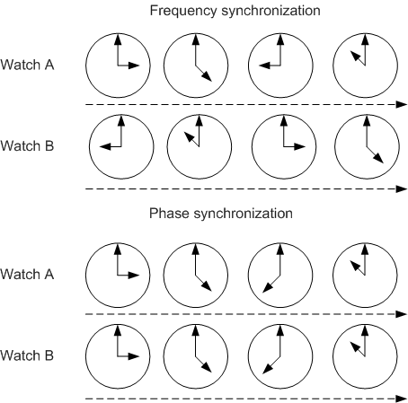
Frequency synchronization, also called clock synchronization, indicates that signals have the same frequency and a fixed phase difference. That is, signals are sent or received at an average rate. All devices on a communications network operate at the same rate.
Phase synchronization
Phase synchronization, also called time synchronization, indicates that both frequencies and phases of signals are consistent. That is, the phase offset between signals is always 0.
Figure 1 illustrates the difference between frequency synchronization and phase synchronization. If Watch A and Watch B show different time but maintain a constant time difference, for example 6 hours, this is called frequency synchronization. If Watch A and Watch B maintain the same time, this is called phase synchronization.
Synchronization Modes
Two clock synchronization modes are available on a communications network: pseudo synchronization and master-slave synchronization.
Pseudo Synchronization
In pseudo synchronization mode, each switching site has its own highly accurate and stable clock. The sites do not synchronize their clocks with each other. A difference may exist in the clock frequency and phase among the clocks of the switching sites. However, small differences generally do not affect service transmission and can be ignored. Pseudo synchronization is often used on communications networks between countries. Caesium clocks are usually used in countries.
Master-Slave Synchronization
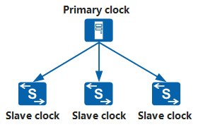
Direct master-slave synchronization
Figure 2 shows direct master-slave synchronization. All slave clocks synchronize with the master clock. Direct master-slave synchronization applies to simple networks.Hierarchical master-slave synchronization
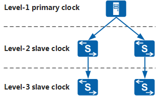
Figure 3 shows hierarchical master-slave synchronization. In this mode, the clocks are classified into three stratum: stratum-1 master clock, stratum-2 slave clock, and stratum-3 slave clock. The stratum-2 slave clock synchronizes with the stratum-1 master clock, and the stratum-3 slave clock synchronizes with the stratum-2 slave clock. Hierarchical master-slave synchronization applies to large and complicated networks.
To improve master-slave synchronization reliability, two master clocks can be deployed: one as the active master clock, and the other as the standby master clock. Under normal circumstances, all network elements, including the standby master clock, trace the active master clock. If the active master clock becomes faulty, the standby master clock takes over as the reference clock for the entire network. After the fault is rectified, the original active-standby relationship is resumed.
Fundamentals
- In the transmit direction: Device1 traces the high-precision clock (master clock) and injects the clock information into the PHY chip of an Ethernet interface card. The PHY chip carries the clock information in the serial code stream of the Ethernet line to transmit the information to the downstream node.
- In the receive direction: The PHY chip of the Ethernet interface card on Device2 extracts clock information from the serial code stream of the Ethernet line, and then sends the clock information to the clock chip. The clock chip selects the most precise clock (or uses the manually or forcibly specified clock) as the reference clock source based on the automatic clock source selection algorithm and sends the clock source to the system phase-locked loop (PLL). After the PLL traces the reference clock source, the PHY chip of the Ethernet interface card transmits the generated high-precision system clock to downstream devices, and other functions (such as the MAC module) of the local device use clock signals.

Comparisons between synchronous Ethernet and other clock synchronization protocols
Clock Protocol |
Whether Frequency Synchronization Is Supported |
Whether Time Synchronization Is Supported |
Time Synchronization Accuracy |
Signal Transmission Mode |
|---|---|---|---|---|
NTP |
No |
Yes |
Millisecond accuracy |
Time signals are transmitted using NTP packets. |
Synchronous Ethernet |
Yes |
No |
- |
Clock signals are transmitted using serial data streams at the physical layer, without affecting upper-layer services and CPU performance. |
PTP |
Yes |
Yes |
Sub-microsecond accuracy |
Clock and time signals are transmitted using PTP packets, and higher time accuracy is achieved with the assistance of hardware. |