Typical Networking for Synchronous Ethernet
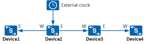
Chain Networking
In Figure 1, Device1, Device2, Device3, and Device4 form a chain topology over Ethernet links. Device2 is a switch connected to an external clock. Devices connected to the switch trace the clock of Device2.
Device1, Device2, Device3, and Device4 complete time synchronization with the external clock using the following method:
- Device2 extracts clock information from the bit streams input from the external clock, embeds the clock information into Ethernet bit streams, and transmits the Ethernet bit streams to Device1 and Device3.
- Device1 extracts clock information from the Ethernet bit streams received from E-side interfaces as the local clock information.
- Device3 extracts clock information from the Ethernet bit streams received from W-side interfaces, embeds the clock information into Ethernet bit streams, and transmits the Ethernet bit streams to Device4.
- Device4 extracts clock information from the Ethernet bit streams received from W-side interfaces as the local clock information.
Regardless of whether the upper-level device works in tracing, holding, or free mode, the lower-level device traces the clock information embedded into Ethernet bit streams on the upper-level device. Therefore, in chain networking, deterioration of Device2's clock performance negatively affects the clock performance of the entire network.
Degradation of clock information may occur if the information is transmitted to a faraway endpoint or multiple transit points must be traversed. To address this issue, configure two reference clocks that maintain synchronization and have the same SSM quality level. In this manner, some devices trace one reference clock, and other devices trace the other reference clock, ensuring the quality of clock signals received by the endpoint.
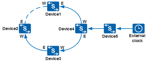
Ring Networking
In Figure 2, Device1, Device2, Device3, Device4, Device5, and Device6 form a ring topology over Ethernet links. Device1 is a switch connected to an external clock, and devices connected to the switch trace the clock of Device1.
The clock tracing mode of the devices connected to the switch in chain networking is similar to that in ring networking. The difference is that devices can extract clock information from Ethernet bit streams received by two line interfaces. To mitigate the impact that the number of transit points and transmission distance has on clock signals, the devices connected to the switch extract clock information over the shortest path and from the interface with the fewest transit points based on the clock source selection algorithm. If two or more interfaces used to receive clock signals have the same path length and number of transit points, the switch selects one of these interfaces to trace clock signals. For example, Device5 traces the clock through the W-side interface, and Device4 traces the clock through the E-side interface.
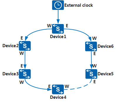
Hybrid Networking
In Figure 3, Device1, Device2, Device3, and Device4 form a ring network topology over Ethernet links, and Device4 and Device5 form a chain network topology over Ethernet links. Device5 is a switch connected to an external clock, and devices connected to the switch trace the clock of Device5.
The clock tracing mode of the devices connected to the switch in hybrid networking is similar to that in ring networking and chain networking. Device5 extracts clock information from the bit streams input from the external clock, embeds the clock information into Ethernet bit streams, and transmits the Ethernet bit streams to downstream devices.