Example for Configuring Link Aggregation in LACP Mode
Networking Requirements
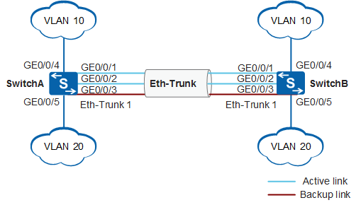
In Figure 1, SwitchA and SwitchB connect to devices in VLAN 10 and VLAN 20 through Ethernet links, and heavy traffic is transmitted between SwitchA and SwitchB. The link between SwitchA and SwitchB is required to provide high bandwidth to implement inter-VLAN communication. Link aggregation in LACP mode is configured on SwitchA and SwitchB to improve the bandwidth and reliability. The following requirements must be met:
Two active links implement load balancing.
One link functions as the backup link. When a fault occurs on an active link, the backup link replaces the faulty link to maintain reliable data transmission.
Devices in the same VLAN can communicate.
Configuration Roadmap
The configuration roadmap is as follows:
Create an Eth-Trunk and configure the Eth-Trunk to work in LACP mode to implement link aggregation.
Add member interfaces to the Eth-Trunk.
Set the LACP system priority and determine the Actor so that the Partner selects active interfaces based on the Actor interface priority.
Set the upper threshold for the number of active interfaces to improve reliability.
Set LACP interface priorities and determine active interfaces so that interfaces with higher priorities are selected as active interfaces.
Create VLANs and add interfaces to the VLANs.
Procedure
- Create Eth-Trunk 1 on SwitchA and configure Eth-Trunk 1 to work in LACP mode. The configuration of SwitchB is similar to the configuration of SwitchA, and is not mentioned here.
<HUAWEI> system-view
[HUAWEI] sysname SwitchA
[SwitchA] interface eth-trunk 1
[SwitchA-Eth-Trunk1] mode lacp
[SwitchA-Eth-Trunk1] quit
- Add member interfaces to Eth-Trunk 1 on SwitchA. The configuration of SwitchB is similar to the configuration of SwitchA, and is not mentioned here.
[SwitchA] interface gigabitethernet 0/0/1
[SwitchA-GigabitEthernet0/0/1] eth-trunk 1
[SwitchA-GigabitEthernet0/0/1] quit
[SwitchA] interface gigabitethernet 0/0/2
[SwitchA-GigabitEthernet0/0/2] eth-trunk 1
[SwitchA-GigabitEthernet0/0/2] quit
[SwitchA] interface gigabitethernet 0/0/3
[SwitchA-GigabitEthernet0/0/3] eth-trunk 1
[SwitchA-GigabitEthernet0/0/3] quit
- Set the system priority on SwitchA to 100 so that SwitchA becomes the Actor.
[SwitchA] lacp priority 100 - On SwitchA, set the upper threshold for the number of active interfaces to 2.
[SwitchA] interface eth-trunk 1
[SwitchA-Eth-Trunk1] max active-linknumber 2
[SwitchA-Eth-Trunk1] quit
- Set the LACP interface priority and determine active links on SwitchA.
[SwitchA] interface gigabitethernet 0/0/1
[SwitchA-GigabitEthernet0/0/1] lacp priority 100
[SwitchA-GigabitEthernet0/0/1] quit
[SwitchA] interface gigabitethernet 0/0/2
[SwitchA-GigabitEthernet0/0/2] lacp priority 100
[SwitchA-GigabitEthernet0/0/2] quit
- Create VLANs and add interfaces to the VLANs.
# Create VLAN 10 and VLAN 20 and add interfaces to them. The configuration of SwitchB is similar to the configuration of SwitchA, and is not mentioned here.
[SwitchA] vlan batch 10 20
[SwitchA] interface gigabitethernet 0/0/4
[SwitchA-GigabitEthernet0/0/4] port link-type trunk
[SwitchA-GigabitEthernet0/0/4] port trunk allow-pass vlan 10
[SwitchA-GigabitEthernet0/0/4] quit
[SwitchA] interface gigabitethernet 0/0/5
[SwitchA-GigabitEthernet0/0/5] port link-type trunk
[SwitchA-GigabitEthernet0/0/5] port trunk allow-pass vlan 20
[SwitchA-GigabitEthernet0/0/5] quit
# Configure Eth-Trunk 1 to allow packets from VLAN 10 and VLAN 20 to pass through. The configuration of SwitchB is similar to the configuration of SwitchA, and is not mentioned here.
[SwitchA] interface eth-trunk 1
[SwitchA-Eth-Trunk1] port link-type trunk
[SwitchA-Eth-Trunk1] port trunk allow-pass vlan 10 20
[SwitchA-Eth-Trunk1] quit
- Verify the configuration.
# Check information about the Eth-Trunk of the switches and check whether negotiation is successful on the link.
[SwitchA] display eth-trunk 1
Eth-Trunk1's state information is:
Local:
LAG ID: 1                       WorkingMode: LACP
Preempt Delay: Disabled         Hash arithmetic: According to SIP-XOR-DIP
System Priority: 100            System ID: 00e0-fca8-0417
Least Active-linknumber: 1      Max Active-linknumber: 2
Operate status: up              Number Of Up Port In Trunk: 2
--------------------------------------------------------------------------------
ActorPortName                    Status     PortType PortPri   PortNo PortKey   PortState  Weight
GigabitEthernet0/0/1             Selected  1GE       100      6145    2865      11111100     1
GigabitEthernet0/0/2             Selected  1GE       100      6146    2865      11111100     1
GigabitEthernet0/0/3             Unselect  1GE       32768    6147    2865      11100000     1

Partner:
--------------------------------------------------------------------------------
ActorPortName                     SysPri    SystemID    PortPri PortNo PortKey   PortState
GigabitEthernet0/0/1              32768  00e0-fca6-7f85  32768     6145   2609      11111100
GigabitEthernet0/0/2              32768  00e0-fca6-7f85  32768     6146   2609      11111100
GigabitEthernet0/0/3              32768  00e0-fca6-7f85  32768     6147   2609      11110000
[SwitchB] display eth-trunk 1
Eth-Trunk1's state information is:
Local:
LAG ID: 1                      WorkingMode: LACP
Preempt Delay: Disabled        Hash arithmetic: According to SIP-XOR-DIP
System Priority: 32768         System ID: 00e0-fca6-7f85
Least Active-linknumber: 1     Max Active-linknumber: 8
Operate status: up             Number Of Up Port In Trunk: 2
--------------------------------------------------------------------------------
ActorPortName                   Status     PortType    PortPri   PortNo  PortKey   PortState  Weight
GigabitEthernet0/0/1            Selected  1GE        32768      6145    2609      11111100     1
GigabitEthernet0/0/2            Selected  1GE        32768      6146    2609      11111100     1
GigabitEthernet0/0/3            Unselect  1GE        32768      6147    2609      11100000     1

Partner:
--------------------------------------------------------------------------------
ActorPortName                     SysPri    SystemID     PortPri  PortNo  PortKey   PortState
GigabitEthernet0/0/1              100    00e0-fca8-0417  100      6145     2865      11111100
GigabitEthernet0/0/2              100    00e0-fca8-0417  100      6146     2865      11111100
GigabitEthernet0/0/3              100    00e0-fca8-0417  32768    6147     2865      11110000
The preceding information shows that the LACP system priority of SwitchA is 100, which is higher than the LACP system priority of SwitchB. Member interfaces GigabitEthernet0/0/1 and GigabitEthernet0/0/2 become the active interfaces and are in Selected state. Interface GigabitEthernet0/0/3 is in Unselect state. Two links are active and work in load balancing mode, and one link is the backup link.
Configuration Files
SwitchA configuration file
#
sysname SwitchA
#
vlan batch 10 20
#
lacp priority 100
#
interface Eth-Trunk1
 port link-type trunk
 port trunk allow-pass vlan 10 20
 mode lacp
 max active-linknumber 2
#
interface GigabitEthernet0/0/1
 eth-trunk 1
 lacp priority 100
#
interface GigabitEthernet0/0/2
 eth-trunk 1
 lacp priority 100
#
interface GigabitEthernet0/0/3
 eth-trunk 1
#
interface GigabitEthernet0/0/4
 port link-type trunk
 port trunk allow-pass vlan 10
#
interface GigabitEthernet0/0/5
 port link-type trunk
 port trunk allow-pass vlan 20
#
return
SwitchB configuration file
#
sysname SwitchB
#
vlan batch 10 20
#
interface Eth-Trunk1
 port link-type trunk
 port trunk allow-pass vlan 10 20
 mode lacp
#
interface GigabitEthernet0/0/1
 eth-trunk 1
#
interface GigabitEthernet0/0/2
 eth-trunk 1
#
interface GigabitEthernet0/0/3
 eth-trunk 1
#
interface GigabitEthernet0/0/4
 port link-type trunk
 port trunk allow-pass vlan 10
#
interface GigabitEthernet0/0/5
 port link-type trunk
 port trunk allow-pass vlan 20
#
return