Example for Connecting an E-Trunk to a VPLS Network
Overview
Enhanced Trunk (E-Trunk) is an extension to LACP (a link aggregation protocol for a single device) and implements link aggregation among multiple devices. E-Trunk achieves device-level link reliability but not card-level link reliability.
When a CE is dual-homed to a VPLS, VLL, or PWE3 network, an E-Trunk can be configured to protect the links between the CE and PEs and implement backup between PEs. If no E-Trunk is configured, a CE can be connected to only one PE using an Eth-Trunk. If the Eth-Trunk or the PE fails, the CE cannot communicate with the PE. After the E-Trunk is used, the CE can be dual-homed to two PEs to implement backup.
Configuration Notes
- Devices must use link aggregation in LACP mode.
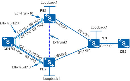
In Figure 1, the E-Trunk configuration on PE1 and PE2 must be the same. The Eth-Trunks between PE1 and CE1 and between PE2 and CE1 must use the same rate and duplex mode (key values must be the same) and join the same E-Trunk. After the Eth-Trunks are added to the E-Trunk, ensure that the LACP priorities and system IDs of PE1 and PE2 are the same. On CE1, interfaces directly connected to PE1 and PE2 must be added to the same Eth-Trunk. The Eth-Trunk can have a different Eth-Trunk ID from that on the PEs. For example, the CE is configured with Eth-Trunk 20, while both PEs are configured with Eth-Trunk 10.
You must specify an IP address (loopback address recommended) for each PE to ensure Layer 3 connectivity. Ensure that the peer IP address of a PE is the local IP address of the other PE.
The E-Trunk must be bound to a BFD session.
You must set the same protocol packet password for PE1 and PE2.
For applicable product models and versions, see Applicable Product Models and Versions.

For details about software mappings, visit Hardware Query Tool and search for the desired product model.
Networking Requirements
If no E-Trunk is configured, a CE can be connected to only one PE using an Eth-Trunk. If the Eth-Trunk or the PE fails, the CE cannot communicate with the PE. After an E-Trunk is configured, the CE can be dual-homed to PEs. E-Trunk achieves device-level link reliability but not card-level link reliability.
In Figure 1, CE1 is connected to PE1 and PE2 using two Eth-Trunks in LACP mode and is dual-homed to a VPLS network.
Initially, CE1 communicates with CE2 on the VPLS network through PE1. If PE1 or the Eth-Trunk between CE1 and PE1 fails, CE1 cannot communicate with CE2. To prevent service interruption, configure an E-Trunk on PE1 and PE2. When communication between CE1 and PE1 fails, traffic is switched to PE2 so that CE1 can communicate with CE2 through PE2. When PE1 or the Eth-Trunk between CE1 and PE1 recovers, traffic is switched back to PE1.
The E-Trunk implements backup of link aggregation groups (LAGs) between PE1 and PE2 and therefore improves network reliability.
Switch |
Interface |
Layer 3 Interface |
IP Address |
|---|---|---|---|
PE1 |
GigabitEthernet1/0/1 |
- |
- |
- |
GigabitEthernet1/0/2 |
- |
- |
- |
GigabitEthernet1/0/3 |
VLANIF 100 |
10.1.1.1/24 |
- |
Loopback1 |
- |
1.1.1.9/32 |
PE2 |
GigabitEthernet1/0/1 |
- |
- |
- |
GigabitEthernet1/0/2 |
- |
- |
- |
GigabitEthernet1/0/3 |
VLANIF 200 |
10.1.2.1/24 |
- |
Loopback1 |
- |
2.2.2.9/32 |
PE3 |
GigabitEthernet1/0/1 |
VLANIF 100 |
10.1.1.2/24 |
- |
GigabitEthernet1/0/2 |
VLANIF 200 |
10.1.2.2/24 |
- |
GigabitEthernet1/0/3 |
GigabitEthernet1/0/3.1 |
- |
- |
Loopback1 |
- |
3.3.3.9/32 |
CE1 |
GigabitEthernet1/0/1 |
- |
- |
- |
GigabitEthernet1/0/2 |
- |
- |
- |
GigabitEthernet1/0/3 |
- |
- |
- |
GigabitEthernet1/0/4 |
- |
- |
CE2 |
GigabitEthernet1/0/3 |
- |
- |
Configuration Roadmap
The configuration roadmap is as follows:
Configure an E-Trunk.
Create Eth-Trunks in LACP mode between CE1 and PE1 and between CE1 and PE2. Add member interfaces to the Eth-Trunks.
Create an E-Trunk on PE1 and PE2 and add the two Eth-Trunks in LACP mode to the E-Trunk.
Set E-Trunk parameters:
E-Trunk priority
LACP system ID and LACP priority of the E-Trunk
Interval at which Hello packets are sent
Time multiplier for detecting Hello packets
IP addresses of the local and remote ends
- Bind the E-Trunk to a BFD session.
- Configure CE1 to connect to the VPLS network as follows:
Configure a routing protocol on the backbone network to implement the interworking between devices.
Configure basic MPLS functions and LDP.
Enable MPLS L2VPN on PEs.
Configure a VSI and specify LDP as the signaling protocol.
Create Eth-Trunk sub-interfaces and bind the VSI to the sub-interfaces.
Procedure
- Configure VLANs and IP addresses on the PW-side interfaces according to Figure 1. Configure a routing protocol on the backbone network to implement the interworking between devices. OSPF is used in this example.
# Configure aggregation switch PE1.
<HUAWEI> system-view
[HUAWEI] sysname PE1
[PE1] vlan batch 100
[PE1] interface gigabitethernet 1/0/3
[PE1-GigabitEthernet1/0/3] port link-type trunk
[PE1-GigabitEthernet1/0/3] port trunk allow-pass vlan 100
[PE1-GigabitEthernet1/0/3] quit
[PE1] interface vlanif 100
[PE1-Vlanif100] ip address 10.1.1.1 24
[PE1-Vlanif100] quit
[PE1] interface loopback 1
[PE1-LoopBack1] ip address 1.1.1.9 32
[PE1-LoopBack1] quit
[PE1] ospf 1
[PE1-ospf-1] area 0
[PE1-ospf-1-area-0.0.0.0] network 1.1.1.9 0.0.0.0
[PE1-ospf-1-area-0.0.0.0] network 10.1.1.0 0.0.0.255
[PE1-ospf-1-area-0.0.0.0] quit
[PE1-ospf-1] quit
# Configure aggregation switch PE2.
<HUAWEI> system-view
[HUAWEI] sysname PE2
[PE2] vlan batch 200
[PE2] interface gigabitethernet 1/0/3
[PE2-GigabitEthernet1/0/3] port link-type trunk
[PE2-GigabitEthernet1/0/3] port trunk allow-pass vlan 200
[PE2-GigabitEthernet1/0/3] quit
[PE2] interface vlanif 200
[PE2-Vlanif200] ip address 10.1.2.1 24
[PE2-Vlanif200] quit
[PE2] interface loopback 1
[PE2-LoopBack1] ip address 2.2.2.9 32
[PE2-LoopBack1] quit
[PE2] ospf 1
[PE2-ospf-1] area 0
[PE2-ospf-1-area-0.0.0.0] network 2.2.2.9 0.0.0.0
[PE2-ospf-1-area-0.0.0.0] network 10.1.2.0 0.0.0.255
[PE2-ospf-1-area-0.0.0.0] quit
[PE2-ospf-1] quit
# Configure aggregation switch PE3.
<HUAWEI> system-view
[HUAWEI] sysname PE3
[PE3] vlan batch 100 200
[PE3] interface gigabitethernet 1/0/1
[PE3-GigabitEthernet1/0/1] port link-type trunk
[PE3-GigabitEthernet1/0/1] port trunk allow-pass vlan 100
[PE3-GigabitEthernet1/0/1] quit
[PE3] interface gigabitethernet 1/0/2
[PE3-GigabitEthernet1/0/2] port link-type trunk
[PE3-GigabitEthernet1/0/2] port trunk allow-pass vlan 200
[PE3-GigabitEthernet1/0/2] quit
[PE3] interface vlanif 100
[PE3-Vlanif100] ip address 10.1.1.2 24
[PE3-Vlanif100] quit
[PE3] interface vlanif 200
[PE3-Vlanif200] ip address 10.1.2.2 24
[PE3-Vlanif200] quit
[PE3] interface loopback 1
[PE3-LoopBack1] ip address 3.3.3.9 32
[PE3-LoopBack1] quit
[PE3] ospf 1
[PE3-ospf-1] area 0
[PE3-ospf-1-area-0.0.0.0] network 3.3.3.9 0.0.0.0
[PE3-ospf-1-area-0.0.0.0] network 10.1.1.0 0.0.0.255
[PE3-ospf-1-area-0.0.0.0] network 10.1.2.0 0.0.0.255
[PE3-ospf-1-area-0.0.0.0] quit
[PE3-ospf-1] quit
After the configuration is complete, PE1, PE2, and PE3 use OSPF to discover IP routes to each other's Loopback1 interface, and can ping one another. Run the display ip routing-table command on PE1, PE2, and PE3 to determine whether the PEs have learned the routes to one another.
- The AC-side interface and PW-side interface of a PE cannot be added to the same VLAN; otherwise, a loop may occur.
- When configuring OSPF, configure PE1, PE2, and PE3 to advertise 32-bit loopback addresses.
- Configure Eth-Trunks in LACP mode on user-side switch CE1, PE1, and PE2, and add member interfaces to the Eth-Trunks. Configure Layer 2 forwarding on CE1.
# Configure CE1.
<HUAWEI> system-view
[HUAWEI] sysname CE1
[CE1] vlan batch 10
[CE1] interface eth-trunk 20 //Create Eth-Trunk 20 and enter the view of Eth-Trunk 20.
[CE1-Eth-Trunk20] port link-type trunk //Set the link type of the interface to trunk.
[CE1-Eth-Trunk20] port trunk allow-pass vlan 10 //Add Eth-Trunk 20 to VLAN 10.
[CE1-Eth-Trunk20] mode lacp //Configure Eth-Trunk 20 to work in LACP mode.
[CE1-Eth-Trunk20] trunkport GigabitEthernet 1/0/1 to 1/0/4 //Add GE1/0/1 to GE1/0/4 to Eth-Trunk20.
[CE1-Eth-Trunk20] quit
# Configure PE1.
[PE1] interface eth-trunk 10 //Create Eth-Trunk 10 and enter the view of Eth-Trunk 10.
[PE1-Eth-Trunk10] port link-type trunk //Set the link type of the interface to trunk.
[PE1-Eth-Trunk10] mode lacp //Configure Eth-Trunk 10 to work in LACP mode.
[PE1-Eth-Trunk10] trunkport GigabitEthernet 1/0/1 to 1/0/2 //Add GE1/0/1 and GE1/0/2 to Eth-Trunk10.
[PE1-Eth-Trunk10] quit
# Configure PE2.
[PE2] interface eth-trunk 10 //Create Eth-Trunk 10 and enter the view of Eth-Trunk 10.
[PE2-Eth-Trunk10] port link-type trunk //Set the link type of the interface to trunk.
[PE2-Eth-Trunk10] mode lacp //Configure Eth-Trunk 10 to work in LACP mode.
[PE2-Eth-Trunk10] trunkport GigabitEthernet 1/0/1 to 1/0/2 //Add GE1/0/1 and GE1/0/2 to Eth-Trunk10.
[PE2-Eth-Trunk10] quit
- Create an E-Trunk and set the LACP priority, LACP system ID, E-Trunk priority, time multiplier for detecting hello packets, interval at which hello packets are sent, and local and remote IP addresses.
# Configure PE1.
[PE1] e-trunk 1 //Create E-Trunk 1 and enter the view of E-Trunk 1.
[PE1-e-trunk-1] quit
[PE1] lacp e-trunk priority 1 //Set the LACP priority of E-Trunk 1 to 1.
[PE1] lacp e-trunk system-id 00E0-FC00-0000 //Set the LACP system ID of E-Trunk 1 to 00E0-FC00-0000.
[PE1] e-trunk 1 //Enter the view of E-Trunk 1.
[PE1-e-trunk-1] priority 10 //Set the priority of E-Trunk 1 to 10.
[PE1-e-trunk-1] timer hold-on-failure multiplier 3 //Set the time multiplier for detecting hello packets to 3.
[PE1-e-trunk-1] timer hello 9 //Set the interval at which hello packets are sent to 9 ms.
[PE1-e-trunk-1] peer-address 2.2.2.9 source-address 1.1.1.9 //Set the remote IP address to 2.2.2.9 and local IP address to 1.1.1.9.
[PE1-e-trunk-1] quit
# Configure PE2.
[PE2] e-trunk 1 //Create E-Trunk 1 and enter the view of E-Trunk 1.
[PE2-e-trunk-1] quit
[PE2] lacp e-trunk priority 1 //Set the LACP priority of E-Trunk 1 to 1.
[PE2] lacp e-trunk system-id 00E0-FC00-0000 //Set the LACP system ID of E-Trunk 1 to 00E0-FC00-0000.
[PE2] e-trunk 1 //Enter the view of E-Trunk 1.
[PE2-e-trunk-1] priority 20 //Set the priority of E-Trunk 1 to 20.
[PE2-e-trunk-1] timer hold-on-failure multiplier 3 //Set the time multiplier for detecting hello packets to 3.
[PE2-e-trunk-1] timer hello 9 //Set the interval at which hello packets are sent to 9 ms.
[PE2-e-trunk-1] peer-address 1.1.1.9 source-address 2.2.2.9 //Set the remote IP address to 1.1.1.9 and local IP address to 2.2.2.9.
[PE2-e-trunk-1] quit
- Add the Eth-Trunks in LACP mode to the E-Trunk.
# Configure PE1.
[PE1] interface eth-trunk 10 //Enter the view of Eth-Trunk 10.
[PE1-Eth-Trunk10] e-trunk 1 //Add Eth-Trunk 10 to E-Trunk 1.
[PE1-Eth-Trunk10] quit
# Configure PE2.
[PE2] interface eth-trunk 10 //Enter the view of Eth-Trunk 10.
[PE2-Eth-Trunk10] e-trunk 1 //Add Eth-Trunk 10 to E-Trunk 1.
[PE2-Eth-Trunk10] quit
- Bind the E-Trunk to a BFD session.
Create a BFD session.
# Configure PE1.
[PE1] bfd //Enable BFD.
[PE1-bfd] quit
[PE1] bfd hello1 bind peer-ip 2.2.2.9 source-ip 1.1.1.9 //Create a BFD session named hello1 and bind the BFD session to remote IP address 2.2.2.9 and local IP address 1.1.1.9.
[PE1-bfd-session-hello1] discriminator local 1 //Set the local discriminator to 1.
[PE1-bfd-session-hello1] discriminator remote 2 //Set the remote discriminator to 2.
[PE1-bfd-session-hello1] commit //Commit the BFD session configuration.
[PE1-bfd-session-hello1] quit
The IP addresses of the local and remote ends of a BFD session must be the same as those of the E-Trunk.
# Configure PE2.
[PE2] bfd
[PE2-bfd] quit
[PE2] bfd hello2 bind peer-ip 1.1.1.9 source-ip 2.2.2.9 //Create a BFD session named hello2 and bind the BFD session to remote IP address 1.1.1.9 and local IP address 2.2.2.9.
[PE2-bfd-session-hello2] discriminator local 2 //Set the local discriminator to 2.
[PE2-bfd-session-hello2] discriminator remote 1 //Set the remote discriminator to 1.
[PE2-bfd-session-hello2] commit //Commit the BFD session configuration.
[PE2-bfd-session-hello2] quit
Bind E-Trunk 1 to the BFD session.
# Configure PE1.
[PE1] e-trunk 1 //Enter the view of E-Trunk 1.
[PE1-e-trunk-1] e-trunk track bfd-session session-name hello1 //Bind E-Trunk 1 to the BFD session hello1.
[PE1-e-trunk-1] quit
# Configure PE2.
[PE2] e-trunk 1 //Enter the view of E-Trunk 1.
[PE2-e-trunk-1] e-trunk track bfd-session session-name hello2 //Bind E-Trunk 1 to the BFD session hello2.
[PE2-e-trunk-1] quit
- Configure PEs so that CE1 can access the VPLS network.
Configure basic MPLS functions and LDP on PE1, PE2, and PE3.
# Configure PE1.
[PE1] mpls lsr-id 1.1.1.9 //Set the LSR ID to 1.1.1.9.
[PE1] mpls //Enable global MPLS.
[PE1-mpls] quit
[PE1] mpls ldp //Enable global LDP.
[PE1-mpls-ldp] quit
[PE1] interface vlanif 100
[PE1-Vlanif100] mpls //Enable MPLS on an interface.
[PE1-Vlanif100] mpls ldp //Enable LDP on an interface.
[PE1-Vlanif100] quit
# Configure PE2.
[PE2] mpls lsr-id 2.2.2.9 //Set the LSR ID to 2.2.2.9.
[PE2] mpls //Enable global MPLS.
[PE2-mpls] quit
[PE2] mpls ldp //Enable global LDP.
[PE2-mpls-ldp] quit
[PE2] interface vlanif 200
[PE2-Vlanif200] mpls //Enable MPLS on an interface.
[PE2-Vlanif200] mpls ldp //Enable LDP on an interface.
[PE2-Vlanif200] quit
# Configure PE3.
[PE3] mpls lsr-id 3.3.3.9 //Set the LSR ID to 3.3.3.9.
[PE3] mpls //Enable global MPLS.
[PE3-mpls] quit
[PE3] mpls ldp //Enable global LDP.
[PE3-mpls-ldp] quit
[PE3] interface vlanif 100
[PE3-Vlanif100] mpls //Enable MPLS on an interface.
[PE3-Vlanif100] mpls ldp //Enable LDP on an interface.
[PE3-Vlanif100] quit
[PE3] interface vlanif 200
[PE3-Vlanif200] mpls //Enable MPLS on an interface.
[PE3-Vlanif200] mpls ldp //Enable LDP on an interface.
[PE3-Vlanif200] quit
After the configuration is complete, run the display mpls ldp session command on PEs to determine whether the status of the remote LDP peer relationship is Operational. This indicates that remote LDP sessions are set up.
Enable MPLS L2VPN on PE1, PE2, and PE3.
# Configure PE1.
[PE1] mpls l2vpn //Enable global MPLS L2VPN.
[PE1-l2vpn] quit
# Configure PE2.
[PE2] mpls l2vpn //Enable global MPLS L2VPN.
[PE2-l2vpn] quit
# Configure PE3.
[PE3] mpls l2vpn //Enable global MPLS L2VPN.
[PE3-l2vpn] quit
Create a VSI ldp1 on PE1, PE2, and PE3 and specify LDP as the signaling protocol in the VSI.
# Configure PE1.
[PE1] vsi ldp1 static //Create a VSI named ldp1 and configure static member discovery.
[PE1-vsi-ldp1] pwsignal ldp //Set the signaling mode to LDP.
[PE1-vsi-ldp1-ldp] vsi-id 2 //Set the ID of the VSI to 2.
[PE1-vsi-ldp1-ldp] peer 3.3.3.9 //Set the peer address of the VSI to 3.3.3.9.
[PE1-vsi-ldp1-ldp] quit
[PE1-vsi-ldp1] quit
# Configure PE2.
[PE2] vsi ldp1 static //Create a VSI named ldp1 and configure static member discovery.
[PE2-vsi-ldp1] pwsignal ldp //Set the signaling mode to LDP.
[PE2-vsi-ldp1-ldp] vsi-id 2 //Set the ID of the VSI to 2.
[PE2-vsi-ldp1-ldp] peer 3.3.3.9 //Set the peer address of the VSI to 3.3.3.9.
[PE2-vsi-ldp1-ldp] quit
[PE2-vsi-ldp1] quit
# Configure PE3.
[PE3] vsi ldp1 static //Create a VSI named ldp1 and configure static member discovery.
[PE3-vsi-ldp1] pwsignal ldp //Set the signaling mode to LDP.
[PE3-vsi-ldp1-ldp] vsi-id 2 //Set the ID of the VSI to 2.
[PE3-vsi-ldp1-ldp] peer 1.1.1.9 //Set the peer address of the VSI to 1.1.1.9.
[PE3-vsi-ldp1-ldp] peer 2.2.2.9 //Set the peer address of the VSI to 2.2.2.9.
[PE3-vsi-ldp1-ldp] quit
[PE3-vsi-ldp1] quit
Configure Eth-Trunk sub-interfaces on PE1 and PE2, and bind the VSI to the Eth-Trunk sub-interfaces.
# Configure PE1.
[PE1] vcmp role silent
[PE1] interface Eth-Trunk 10.1 //Create Eth-Trunk 10.1 and enter the view of Eth-Trunk 10.1.
[PE1-Eth-Trunk10.1] dot1q termination vid 10 //Set the single VLAN ID for dot1q encapsulation on Eth-Trunk 10.1 to VLAN 10.
[PE1-Eth-Trunk10.1] l2 binding vsi ldp1 //Bind Eth-Trunk 10.1 to the VSI ldp1.
[PE1-Eth-Trunk10.1] quit
# Configure PE2.
[PE2] vcmp role silent
[PE2] interface Eth-Trunk 10.1 //Create Eth-Trunk 10.1 and enter the view of Eth-Trunk 10.1.
[PE2-Eth-Trunk10.1] dot1q termination vid 10 //Set the single VLAN ID for dot1q encapsulation on Eth-Trunk 10.1 to VLAN 10.
[PE2-Eth-Trunk10.1] l2 binding vsi ldp1 //Bind Eth-Trunk 10.1 to the VSI ldp1.
[PE2-Eth-Trunk10.1] quit
Configure a sub-interface on PE3 and bind the VSI to the sub-interface.
# Configure PE3.
[PE3] vcmp role silent
[PE3] interface gigabitethernet 1/0/3.1 //Create GE1/0/3.1 and enter the view of GE1/0/3.1.
[PE3-GigabitEthernet1/0/3.1] dot1q termination vid 10 //Set the single VLAN ID for dot1q encapsulation on GE1/0/3.1 to VLAN 10.
[PE3-GigabitEthernet1/0/3.1] l2 binding vsi ldp1 //Bind GE1/0/3.1 to the VSI ldp1.
[PE3-GigabitEthernet1/0/3.1] quit
- Verify the configuration.
Run the display eth-trunk command on CE1 to check the Eth-Trunk configuration.
Run the display e-trunk command to check information about the E-Trunk.
# Check information about E-Trunk 1 on PE1.
[PE1] display e-trunk 1
                            The E-Trunk information
E-TRUNK-ID : 1                          Revert-Delay-Time (s) : 120
Priority : 10                           System-ID : 00e0-0f74-eb00
Peer-IP : 2.2.2.9                       Source-IP : 1.1.1.9
State : Master                          Causation : PRI
Send-Period (100ms) : 9                 Fail-Time (100ms) : 27
Receive : 41                            Send : 42
RecDrop : 0                             SndDrop : 0
Peer-Priority : 20                      Peer-System-ID : 00e0-3b6c-6100
Peer-Fail-Time (100ms) : 27             BFD-Session : hello1
Description : -
Sequence : Enable
--------------------------------------------------------------------------------
                            The Member information
Type      ID  LocalPhyState  Work-Mode     State   Causation        Remote-ID
Eth-Trunk 10  Up             auto          Master  ETRUNK_MASTER    10
# Check information about E-Trunk 1 on PE2.
[PE2] display e-trunk 1
                            The E-Trunk information
E-TRUNK-ID : 1                          Revert-Delay-Time (s) : 120
Priority : 20                           System-ID : 00e0-3b6c-6100
Peer-IP : 1.1.1.9                       Source-IP : 2.2.2.9
State : Backup                          Causation : PRI
Send-Period (100ms) : 9                 Fail-Time (100ms) : 27
Receive : 43                            Send : 42
RecDrop : 3                             SndDrop : 0
Peer-Priority : 10                      Peer-System-ID : 00e0-0f74-eb00
Peer-Fail-Time (100ms) : 27             BFD-Session : hello2
Description : -
Sequence : Enable
--------------------------------------------------------------------------------
                            The Member information
Type      ID  LocalPhyState  Work-Mode     State   Causation        Remote-ID
Eth-Trunk 10  Down           auto          Backup  ETRUNK_BACKUP    10
The preceding information shows that the E-Trunk priority on PE1 is 10, and the E-Trunk status is Master; the E-Trunk priority on PE2 is 20, and the E-Trunk status is Backup. Device backup is implemented.
Configuration Files
CE1 configuration file
#
sysname CE1
#
vlan batch 10
#
interface Eth-Trunk20
 port link-type trunk
 port trunk allow-pass vlan 10
 mode lacp
#
interface GigabitEthernet1/0/1
 eth-trunk 20
#
interface GigabitEthernet1/0/2
 eth-trunk 20
#
interface GigabitEthernet1/0/3
 eth-trunk 20
#
interface GigabitEthernet1/0/4
 eth-trunk 20
#
return
PE1 configuration file
#
sysname PE1
#
vcmp role silent
#
vlan batch 100
#
lacp e-trunk system-id 00e0-fc00-0000
lacp e-trunk priority 1
#
bfd
#
mpls lsr-id 1.1.1.9
mpls
#
mpls l2vpn
#
vsi ldp1 static
 pwsignal ldp
  vsi-id 2
  peer 3.3.3.9
#
mpls ldp
#
interface Vlanif100
 ip address 10.1.1.1 255.255.255.0
 mpls
 mpls ldp
#
e-trunk 1
 priority 10
 peer-address 2.2.2.9 source-address 1.1.1.9
 timer hello 9
 timer hold-on-failure multiplier 3
 e-trunk track bfd-session session-name hello1
#
interface Eth-Trunk10
 port link-type trunk
 mode lacp
 e-trunk 1
#
interface Eth-Trunk10.1
 dot1q termination vid 10
 l2 binding vsi ldp1
#
interface GigabitEthernet1/0/1
 eth-trunk 10
#
interface GigabitEthernet1/0/2
 eth-trunk 10
#
interface GigabitEthernet1/0/3
 port link-type trunk
 port trunk allow-pass vlan 100
#
interface LoopBack1
 ip address 1.1.1.9 255.255.255.255
#
bfd hello1 bind peer-ip 2.2.2.9 source-ip 1.1.1.9
 discriminator local 1
 discriminator remote 2
 commit
#
ospf 1
 area 0.0.0.0
  network 1.1.1.9 0.0.0.0
  network 10.1.1.0 0.0.0.255
#
return
PE2 configuration file
#
sysname PE2
#
vcmp role silent
#
vlan batch 200
#
lacp e-trunk system-id 00e0-fc00-0000
lacp e-trunk priority 1
#
bfd
#
mpls lsr-id 2.2.2.9
mpls
#
mpls l2vpn
#
vsi ldp1 static
 pwsignal ldp
  vsi-id 2
  peer 3.3.3.9
#
mpls ldp
#
interface Vlanif200
 ip address 10.1.2.1 255.255.255.0
 mpls
 mpls ldp
#
e-trunk 1
 priority 20
 peer-address 1.1.1.9 source-address 2.2.2.9
 timer hello 9
 timer hold-on-failure multiplier 3
 e-trunk track bfd-session session-name hello2
#
interface Eth-Trunk10
 port link-type trunk
 mode lacp
 e-trunk 1
#
interface Eth-Trunk10.1
 dot1q termination vid 10
 l2 binding vsi ldp1
#
interface GigabitEthernet1/0/1
 eth-trunk 10
#
interface GigabitEthernet1/0/2
 eth-trunk 10
#
interface GigabitEthernet1/0/3
 port link-type trunk
 port trunk allow-pass vlan 200
#
interface LoopBack1
 ip address 2.2.2.9 255.255.255.255
#
bfd hello2 bind peer-ip 1.1.1.9 source-ip 2.2.2.9
 discriminator local 2
 discriminator remote 1
 commit
#
ospf 1
 area 0.0.0.0
  network 2.2.2.9 0.0.0.0
  network 10.1.2.0 0.0.0.255
#
return
PE3 configuration file
#
sysname PE3
#
vcmp role silent
#
vlan batch 100 200
#
mpls lsr-id 3.3.3.9
mpls
#
mpls l2vpn
#
vsi ldp1 static
 pwsignal ldp
  vsi-id 2
  peer 1.1.1.9
  peer 2.2.2.9
#
mpls ldp
#
interface Vlanif100
 ip address 10.1.1.2 255.255.255.0
 mpls
 mpls ldp
#
interface Vlanif200
 ip address 10.1.2.2 255.255.255.0
 mpls
 mpls ldp
#
interface GigabitEthernet1/0/1
 port link-type trunk
 port trunk allow-pass vlan 100
#
interface GigabitEthernet1/0/2
 port link-type trunk
 port trunk allow-pass vlan 200
#
interface GigabitEthernet1/0/3.1
 dot1q termination vid 10
 l2 binding vsi ldp1
#
interface LoopBack1
 ip address 3.3.3.9 255.255.255.255
#
ospf 1
 area 0.0.0.0
  network 3.3.3.9 0.0.0.0
  network 10.1.1.0 0.0.0.255
  network 10.1.2.0 0.0.0.255
#
return
Applicable Product Models and Versions
Product |
Product Model |
Software Version |
|---|---|---|
S5700 |
S5700-HI |
V200R001(C00&C01), V200R002C00, V200R003C00, V200R005(C00SPC500&C01&C02) |
S5710-EI |
V200R001C00, V200R002C00, V200R003C00, V200R005(C00&C02) |
|
S5720-EI |
V200R007C00, V200R008C00, V200R009C00, V200R010C00, V200R011C00, V200R011C10, V200R012C00, V200R013C00, V200R019C00, V200R019C10 |
|
S5710-HI |
V200R003C00, V200R005(C00&C02&C03) |
|
S5720-HI |
V200R006C00, V200R007(C00&C10), V200R008C00, V200R009C00, V200R010C00, V200R011C00, V200R011C10, V200R012C00, V200R013C00, V200R019C00, V200R019C10 |
|
S5730-HI |
V200R012C00, V200R013C00, V200R019C00, V200R019C10 |
|
S5731-H |
V200R013C02, V200R019C00, V200R019C10 |
|
S5731-S, S5731S-S |
V200R019C00, V200R019C10 |
|
S5731S-H |
V200R019C00, V200R019C10 |
|
S5732-H |
V200R019C00, V200R019C10 |
|
S6700 |
S6700-EI |
V200R001(C00&C01), V200R002C00, V200R003C00, V200R005(C00&C01&C02) |
S6720-EI |
V200R008C00, V200R009C00, V200R010C00, V200R011C00, V200R011C10, V200R012C00, V200R013C00, V200R019C00, V200R019C10 |
|
S6720S-EI |
V200R009C00, V200R010C00, V200R011C00, V200R011C10, V200R012C00, V200R013C00, V200R019C00, V200R019C10 |
|
S6720-HI |
V200R012C00, V200R013C00, V200R019C00, V200R019C10 |
|
S6730-H |
V200R013C02, V200R019C00, V200R019C10 |
|
S6730S-H |
V200R019C10 |
|
S6730-S, S6730S-S |
V200R019C00, V200R019C10 |
|
S7700 |
S7703, S7706, S7712 |
V200R001(C00&C01), V200R002C00, V200R003C00, V200R005C00, V200R006C00, V200R007C00, V200R008C00, V200R009C00, V200R010C00, V200R011C10, V200R012C00, V200R013C00, V200R013C02, V200R019C00, V200R019C10 |
S7703 PoE |
V200R013C00, V200R019C00, V200R019C10 |
|
S7706 PoE |
V200R013C00, V200R019C00, V200R019C10 |
|
S9700 |
S9703, S9706, S9712 |
V200R001(C00&C01), V200R002C00, V200R003C00, V200R005C00, V200R006C00, V200R007(C00&C10), V200R008C00, V200R009C00, V200R010C00, V200R011C10, V200R012C00, V200R013C00 |