Example for Configuring Ethernet over GRE to Build a Virtual Layer 2 Network
Networking Requirements
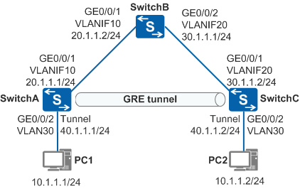
In Figure 1, SwitchA, SwitchB, and SwitchC use the Open Shortest Path First (OSPF) protocol to communicate with each other over the Internet. A GRE tunnel is established between SwitchA and SwitchC. The customer wants to construct a virtual Layer 2 network over the Internet between SwitchA and SwitchC to allow PC1 and PC2 to communicate at Layer 2.
Configuration Roadmap
To meet the preceding requirements, an Ethernet over GRE tunnel needs to be deployed between SwitchA and SwitchC. A VE interface forwards Ethernet packets over the GRE tunnel, enabling Layer 2 communication between PC1 and PC2.
The configuration roadmap is as follows:
Run OSPF on all the switches to implement communication over the Internet.
Create tunnel interfaces on SwitchA and SwitchC to establish a GRE tunnel between them.
Create VE interfaces on SwitchA and SwitchC and add them to a VLAN.
Bind VE interfaces to the GRE tunnel on SwitchA and SwitchC to forward Ethernet packets over the GRE tunnel.
Procedure
- Configure an IP address for each physical interface.
# Configure SwitchA.
<HUAWEI> system-view
[HUAWEI] sysname SwitchA
[SwitchA] vlan batch 10 30
[SwitchA] interface gigabitethernet 0/0/1
[SwitchA-GigabitEthernet0/0/1] port link-type trunk
[SwitchA-GigabitEthernet0/0/1] port trunk allow-pass vlan 10
[SwitchA-GigabitEthernet0/0/1] quit
[SwitchA] interface gigabitethernet 0/0/2
[SwitchA-GigabitEthernet0/0/2] port link-type access
[SwitchA-GigabitEthernet0/0/2] port default vlan 30
[SwitchA-GigabitEthernet0/0/2] quit
[SwitchA] interface vlanif 10
[SwitchA-Vlanif10] ip address 20.1.1.1 24
[SwitchA-Vlanif10] quit
# Configure SwitchB.
<HUAWEI> system-view
[HUAWEI] sysname SwitchB
[SwitchB] vlan batch 10 20
[SwitchB] interface gigabitethernet 0/0/1
[SwitchB-GigabitEthernet0/0/1] port link-type trunk
[SwitchB-GigabitEthernet0/0/1] port trunk allow-pass vlan 10
[SwitchB-GigabitEthernet0/0/1] quit
[SwitchB] interface gigabitethernet 0/0/2
[SwitchB-GigabitEthernet0/0/2] port link-type trunk
[SwitchB-GigabitEthernet0/0/2] port trunk allow-pass vlan 20
[SwitchB-GigabitEthernet0/0/2] quit
[SwitchB] interface vlanif 10
[SwitchB-Vlanif10] ip address 20.1.1.2 24
[SwitchB-Vlanif10] quit
[SwitchB] interface vlanif 20
[SwitchB-Vlanif20] ip address 30.1.1.1 24
[SwitchB-Vlanif20] quit
# Configure SwitchC.
<HUAWEI> system-view
[HUAWEI] sysname SwitchC
[SwitchC] vlan batch 20 30
[SwitchC] interface gigabitethernet 0/0/1
[SwitchC-GigabitEthernet0/0/1] port link-type trunk
[SwitchC-GigabitEthernet0/0/1] port trunk allow-pass vlan 20
[SwitchC-GigabitEthernet0/0/1] quit
[SwitchC] interface gigabitethernet 0/0/2
[SwitchC-GigabitEthernet0/0/2] port link-type access
[SwitchC-GigabitEthernet0/0/2] port default vlan 30
[SwitchC-GigabitEthernet0/0/2] quit
[SwitchC] interface vlanif 20
[SwitchC-Vlanif20] ip address 30.1.1.2 24
[SwitchC-Vlanif20] quit
- Run OSPF on the switches to implement communication over
the Internet.
# Configure SwitchA.
[SwitchA] ospf 1
[SwitchA-ospf-1] area 0
[SwitchA-ospf-1-area-0.0.0.0] network 20.1.1.0 0.0.0.255
[SwitchA-ospf-1-area-0.0.0.0] quit
[SwitchA-ospf-1] quit
# Configure SwitchB.
[SwitchB] ospf 1
[SwitchB-ospf-1] area 0
[SwitchB-ospf-1-area-0.0.0.0] network 20.1.1.0 0.0.0.255
[SwitchB-ospf-1-area-0.0.0.0] network 30.1.1.0 0.0.0.255
[SwitchB-ospf-1-area-0.0.0.0] quit
[SwitchB-ospf-1] quit
# Configure SwitchC.
[SwitchC] ospf 1
[SwitchC-ospf-1] area 0
[SwitchC-ospf-1-area-0.0.0.0] network 30.1.1.0 0.0.0.255
[SwitchC-ospf-1-area-0.0.0.0] quit
[SwitchC-ospf-1] quit
# After the configuration is complete, run the display ip routing-table command on SwitchA and SwitchC. You can find that they have learned the OSPF routes destined for the network segment of the peer.
- Configure tunnel interfaces and create a GRE tunnel.
# Configure SwitchA.
[SwitchA] interface tunnel 1
[SwitchA-Tunnel1] tunnel-protocol gre
[SwitchA-Tunnel1] ip address 40.1.1.1 255.255.255.0
[SwitchA-Tunnel1] source 20.1.1.1
[SwitchA-Tunnel1] destination 30.1.1.2
[SwitchA-Tunnel1] quit
# Configure SwitchC.
[SwitchC] interface tunnel 1
[SwitchC-Tunnel1] tunnel-protocol gre
[SwitchC-Tunnel1] ip address 40.1.1.2 255.255.255.0
[SwitchC-Tunnel1] source 30.1.1.2
[SwitchC-Tunnel1] destination 20.1.1.1
[SwitchC-Tunnel1] quit
# After the configuration is complete, the tunnel interfaces turn Up and can ping each other. A GRE tunnel has been set up between them.
The display on SwitchA is used as an example.
[SwitchA] ping -a 40.1.1.1 40.1.1.2 PING 40.1.1.2: 56 data bytes, press CTRL_C to break Reply from 40.1.1.2: bytes=56 Sequence=1 ttl=255 time=1 ms Reply from 40.1.1.2: bytes=56 Sequence=2 ttl=255 time=1 ms Reply from 40.1.1.2: bytes=56 Sequence=3 ttl=255 time=1 ms Reply from 40.1.1.2: bytes=56 Sequence=4 ttl=255 time=1 ms Reply from 40.1.1.2: bytes=56 Sequence=5 ttl=255 time=1 ms --- 40.1.1.2 ping statistics --- 5 packet(s) transmitted 5 packet(s) received 0.00% packet loss round-trip min/avg/max = 1/1/1 ms - Add VE interfaces to a VLAN. Note that the VE interface
and inbound interface for user-side packets must be added to the same
VLAN.
# Configure SwitchA.
[SwitchA] interface Virtual-Ethernet0/0/1
[SwitchA-Virtual-Ethernet0/0/1] portswitch
[SwitchA-Virtual-Ethernet0/0/1] port link-type trunk
[SwitchA-Virtual-Ethernet0/0/1] undo port trunk allow-pass vlan 1
[SwitchA-Virtual-Ethernet0/0/1] port trunk allow-pass vlan 30
[SwitchA-Virtual-Ethernet0/0/1] quit
# Configure SwitchC.
[SwitchC] interface Virtual-Ethernet0/0/1
[SwitchC-Virtual-Ethernet0/0/1] portswitch
[SwitchC-Virtual-Ethernet0/0/1] port link-type trunk
[SwitchC-Virtual-Ethernet0/0/1] undo port trunk allow-pass vlan 1
[SwitchC-Virtual-Ethernet0/0/1] port trunk allow-pass vlan 30
[SwitchC-Virtual-Ethernet0/0/1] quit
- Bind VE interfaces to the GRE tunnel to forward Ethernet
packets over the GRE tunnel.
# Configure SwitchA.
[SwitchA] interface tunnel 1
[SwitchA-Tunnel1] map interface virtual-ethernet 0/0/1
[SwitchA-Tunnel1] quit
# Configure SwitchC.
[SwitchC] interface tunnel 1
[SwitchC-Tunnel1] map interface virtual-ethernet 0/0/1
[SwitchC-Tunnel1] quit
- Verify the configuration.
After the configurations are complete, PC1 and PC2 can ping each other successfully.
The ping result from PC1 to PC2 is used as an example.
C:\Users\pc1> ping 10.1.1.2
  PING 10.1.1.2: 56  data bytes, press CTRL_C to break
    Reply from 10.1.1.2: bytes=56 Sequence=1 ttl=253 time=72 ms
    Reply from 10.1.1.2: bytes=56 Sequence=2 ttl=253 time=34 ms
    Reply from 10.1.1.2: bytes=56 Sequence=3 ttl=253 time=50 ms
    Reply from 10.1.1.2: bytes=56 Sequence=4 ttl=253 time=50 ms
    Reply from 10.1.1.2: bytes=56 Sequence=5 ttl=253 time=34 ms
  --- 10.1.1.2 ping statistics ---
    5 packet(s) transmitted
    5 packet(s) received
    0.00% packet loss
    round-trip min/avg/max = 34/48/72 ms
Configuration Files
SwitchA configuration file
#
sysname SwitchA
#
vlan batch 10 30
#
interface Vlanif10
 ip address 20.1.1.1 255.255.255.0
#
interface GigabitEthernet0/0/1
 port link-type trunk
 port trunk allow-pass vlan 10
#
interface GigabitEthernet0/0/2
 port link-type access
 port default vlan 30
#
interface Virtual-Ethernet0/0/1
 portswitch
 port link-type trunk
 undo port trunk allow-pass vlan 1
 port trunk allow-pass vlan 30
#
interface Tunnel1
 ip address 40.1.1.1 255.255.255.0
 tunnel-protocol gre
 source 20.1.1.1
 destination 30.1.1.2
 map interface Virtual-Ethernet0/0/1
#
ospf 1
 area 0.0.0.0
  network 20.1.1.0 0.0.0.255
#
return
SwitchB configuration file
#
sysname SwitchB
#
vlan batch 10 20
#
interface Vlanif10
 ip address 20.1.1.2 255.255.255.0
#
interface Vlanif20
 ip address 30.1.1.1 255.255.255.0
#
interface GigabitEthernet0/0/1
 port link-type trunk
 port trunk allow-pass vlan 10
#
interface GigabitEthernet0/0/2
 port link-type trunk
 port trunk allow-pass vlan 20
#
ospf 1
 area 0.0.0.0
  network 20.1.1.0 0.0.0.255
  network 30.1.1.0 0.0.0.255
#
return
SwitchC configuration file
#
sysname SwitchC
#
vlan batch 20 30
#
interface Vlanif20
 ip address 30.1.1.2 255.255.255.0
#
interface GigabitEthernet0/0/1
 port link-type trunk
 port trunk allow-pass vlan 20
#
interface GigabitEthernet0/0/2
 port link-type access
 port default vlan 30
#
interface Virtual-Ethernet0/0/1
 portswitch
 port link-type trunk
 undo port trunk allow-pass vlan 1
 port trunk allow-pass vlan 30
#
interface Tunnel1
 ip address 40.1.1.2 255.255.255.0
 tunnel-protocol gre
 source 30.1.1.2
 destination 20.1.1.1
 map interface Virtual-Ethernet0/0/1
#
ospf 1
 area 0.0.0.0
  network 30.1.1.0 0.0.0.255
#
return