Example for Configuring Ethernet over GRE to Enable Layer 2 Communication Between an AC and a Wireless Gateway
Networking Requirements
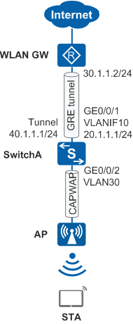
Figure 1 shows typical networking in a wireless city project. APs provide wireless user access; SwitchA functions as the AC to provide AP access and user authentication; the WLAN GW functions as a user gateway to provide functions including IP address assignment and Internet access. There are a large number of APs at this site. To prevent a lot of resources from being consumed by frequent establishment and deletion of many GRE tunnels on the WLAN GW, Ethernet over GRE can be configured between the AC and WLAN GW for Layer 2 communication.
Configuration Roadmap

This example provides only AC-side (SwitchA's) Ethernet over GRE configuration. For the WLAN configuration and WLAN GW's Ethernet over GRE configuration, see the corresponding configuration document.
To meet the preceding requirements, you need to deploy an Ethernet over GRE tunnel between SwitchA and the WLAN GW so that Ethernet packets can be forwarded from a VE interface over a GRE tunnel. This enables Layer 2 communication between the AC and WLAN GW.
The configuration roadmap for deploying an Ethernet over GRE tunnel on the AC is as follows:
Run IGP between all devices for communication on the public network.
Create tunnel interfaces and deploy a GRE tunnel on SwitchA.
Create a VE interface on SwitchA and add this interface to the corresponding VLAN.
On SwitchA, bind the VE interface to the GRE tunnel so that Ethernet packets can be forwarded over the GRE tunnel.
Procedure
- Configure an IP address for each physical interface.
# Configure SwitchA.
<HUAWEI> system-view
[HUAWEI] sysname SwitchA
[SwitchA] vlan batch 10 30
[SwitchA] interface gigabitethernet 0/0/1
[SwitchA-GigabitEthernet0/0/1] port link-type trunk
[SwitchA-GigabitEthernet0/0/1] port trunk allow-pass vlan 10
[SwitchA-GigabitEthernet0/0/1] quit
[SwitchA] interface gigabitethernet 0/0/2
[SwitchA-GigabitEthernet0/0/2] port link-type access
[SwitchA-GigabitEthernet0/0/2] port default vlan 30
[SwitchA-GigabitEthernet0/0/2] quit
[SwitchA] interface vlanif 10
[SwitchA-Vlanif10] ip address 20.1.1.1 24
[SwitchA-Vlanif10] quit
- Configure tunnel interfaces and deploy a GRE tunnel. In
the following configuration, the source and destination interface
addresses of the GRE tunnel are 20.1.1.1 and 30.1.1.2 respectively.
# Configure SwitchA.
[SwitchA] interface tunnel 1
[SwitchA-Tunnel1] tunnel-protocol gre
[SwitchA-Tunnel1] ip address 40.1.1.1 255.255.255.0
[SwitchA-Tunnel1] source 20.1.1.1
[SwitchA-Tunnel1] destination 30.1.1.2
[SwitchA-Tunnel1] quit
- Create a VE interface and add it to the corresponding VLAN.
Ensure that this VE interface and the inbound interface of user packets
are added to the same VLAN.
# Configure SwitchA.
[SwitchA] interface Virtual-Ethernet0/0/1
[SwitchA-Virtual-Ethernet0/0/1] portswitch
[SwitchA-Virtual-Ethernet0/0/1] port link-type trunk
[SwitchA-Virtual-Ethernet0/0/1] undo port trunk allow-pass vlan 1
[SwitchA-Virtual-Ethernet0/0/1] port trunk allow-pass vlan 30
[SwitchA-Virtual-Ethernet0/0/1] quit
- Bind the VE interface to GRE tunnel so that Ethernet packets
can be forwarded over the GRE tunnel.
# Configure SwitchA.
[SwitchA] interface tunnel 1
[SwitchA-Tunnel1] map interface virtual-ethernet 0/0/1
[SwitchA-Tunnel1] quit
- Verify the Configuration
After the configuration is complete, wireless users can communicate with the WLAN GW at Layer 2. Through this WLAN GW, wireless user traffic can be forwarded at Layer 3 and wireless users can access the public network.
Configuration Files
SwitchA configuration file
#
sysname SwitchA
#
vlan batch 10 30
#
interface Vlanif10
 ip address 20.1.1.1 255.255.255.0
#
interface GigabitEthernet0/0/1
 port link-type trunk
 port trunk allow-pass vlan 10
#
interface GigabitEthernet0/0/2
 port link-type access
 port default vlan 30
#
interface Virtual-Ethernet0/0/1
 portswitch
 port link-type trunk
 undo port trunk allow-pass vlan 1
 port trunk allow-pass vlan 30
#
interface Tunnel1
 ip address 40.1.1.1 255.255.255.0
 tunnel-protocol gre
 source 20.1.1.1
 destination 30.1.1.2
 map interface virtual-ethernet 0/0/1
#
return