Configuring a Tunnel Interface
Context
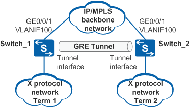
A GRE tunnel is established between two tunnel interfaces, therefore you need to configure a tunnel interface on devices at both ends of a tunnel. Then, set the protocol type to GRE, specify the tunnel source address (or interface) and tunnel destination address, and specify IP addresses for tunnel interfaces.
Tunnel source address (or interface)
Indicates the source address or interface used for packet transmission. The tunnel source interface is the physical interface from which encapsulated packets are sent, that is, VLANIF100 on Switch_1. The tunnel source address is the IP address of the physical interface from which encapsulated packets are sent, that is, the IP address of VLANIF100 on Switch_1.
Tunnel destination address
Indicates the destination address for packet transmission. The tunnel destination address is the IP address of the physical interface to which encapsulated packets are sent, that is, the IP address of VLANIF100 on Switch_2.
IP address of the tunnel interface
Indicates an IP address assigned to the tunnel interface. A dynamic or static routing protocol uses this IP address to advertise the tunnel interface. The IP address of the tunnel interface may be a public network address or not. It can also be an IP address borrowed from another interface to save IP addresses. When the tunnel interface borrows an IP address from another interface, you cannot enable a dynamic routing protocol on the tunnel interface because it does not have an IP address of its own. You must configure a static route to ensure connectivity between the devices.
Procedure
- Run system-view
The system view is displayed.
- Run interface tunnel interface-number
A tunnel interface is created and the tunnel interface view is displayed.
- Run tunnel-protocol gre
The protocol type of the tunnel interface is set to GRE.
- Run source { source-ip-address | interface-type interface-number }
A source address or source interface is specified for the tunnel.
 When configuring the source interface of a tunnel, note the following:
Do not specify the tunnel interface of a GRE tunnel as its own source interface. You can specify the tunnel interface of another tunnel as the source interface.
Do not configure a management interface as the source interface of a tunnel and do not configure the IP address of the management interface as the source address.
- Do not configure a VBDIF interface as the source interface of a tunnel and do not configure the IP address of the VBDIF interface as the source address.
- Run destination [ vpn-instance vpn-instance-name ] dest-ip-address
A destination address is specified for the tunnel.
If a customer edge (CE) is connected to a provider edge (PE) through the GRE tunnel, specify a virtual private network (VPN) instance to add the tunnel interface to a private network routing table when configuring the tunnel's destination address.
Do not configure the IP address of the VBDIF interface as the destination address.
- (Optional) Run mtu mtu
A maximum transmission unit (MTU) is configured for the tunnel interface.
By default, the MTU of a tunnel interface is 1500 bytes.
To change the MTU of a tunnel interface, run the shutdown command and then the undo shutdown command on the interface to make the new MTU take effect.
- (Optional) Run description text
An interface description is provided.
By default, no description is provided for the tunnel interface.
- Run either of the following commands to specify an IP address for the tunnel interface.
Specify an IP address.
Specify an IPv4 address for the tunnel interface when IPv4 networks communicate using the GRE tunnel.
Run ip address ip-address { mask | mask-length } [ sub ]
An IPv4 address is specified for the tunnel interface.
Specify an IPv6 address for the tunnel interface when IPv6 networks communicate using the GRE tunnel.
Run ipv6 address { ipv6-address prefix-length | ipv6-address/prefix-length }
An IPv6 address is specified for the tunnel interface.
Before specifying an IPv6 address for an interface, run the ipv6 command in the system view to enable IPv6 packet forwarding and the ipv6 enable command on the interface to enable the IPv6 function.
Only S5720-HI, S5730-HI, S5731-H, S5731-S, S5731S-H, S5731S-S, S5732-H, S6720-HI, S6730-H, S6730S-H, S6730-S, and S6730S-S support this function.
Run eth-trunk trunk-id
The interface is added to the Eth-Trunk.
The loopback interface must be created before performing this step. For details, see Enabling the Service Loopback Function on an Eth-Trunk in "IPv6 over IPv4 Tunnel Configuration" in the S2720, S5700, and S6700 V200R019C10 Configuration Guide - IP Service.
Borrow an IP address.
Run ip address unnumbered interface interface-type interface-number
The tunnel interface is configured to borrow an IP address.
A tunnel interface cannot borrow an IPv6 address.