Example for Configuring a Static Route for GRE to Implement Interworking Between IPv4 Networks
Networking Requirements
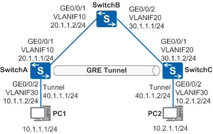
- SwitchA, SwitchB, and SwitchC communicate with each other through a public network. (The OSPF protocol is used in this example.)
- PC1 and PC2 run the IPv4 proprietary protocol and communicate with each other over the public network.
PC1 uses SwitchA and PC2 uses SwitchC as a default gateway.
Configuration Roadmap
To allow PC1 to communicate with PC2, you can configure a direct link between SwitchA and SwitchC. This allows you to set up a GRE tunnel and configure a static route to forward packets through tunnel interfaces to the peer.
The configuration roadmap is as follows:
Run OSPF on the devices to implement interworking among them.
Create tunnel interfaces on SwitchA and SwitchC to set up a GRE tunnel, and configure a static route passing through tunnel interfaces on SwitchA and SwitchC, so that traffic between PC1 and PC2 can be transmitted over the GRE tunnel.
Procedure
- Configure an IP address for each physical interface.
# Configure SwitchA.
<HUAWEI> system-view
[HUAWEI] sysname SwitchA
[SwitchA] vlan batch 10 30
[SwitchA] interface gigabitethernet 0/0/1
[SwitchA-GigabitEthernet0/0/1] port link-type trunk
[SwitchA-GigabitEthernet0/0/1] port trunk allow-pass vlan 10
[SwitchA-GigabitEthernet0/0/1] quit
[SwitchA] interface gigabitethernet 0/0/2
[SwitchA-GigabitEthernet0/0/2] port link-type access
[SwitchA-GigabitEthernet0/0/2] port default vlan 30
[SwitchA-GigabitEthernet0/0/2] quit
[SwitchA] interface vlanif 10
[SwitchA-Vlanif10] ip address 20.1.1.1 24
[SwitchA-Vlanif10] quit
[SwitchA] interface vlanif 30
[SwitchA-Vlanif30] ip address 10.1.1.2 24
[SwitchA-Vlanif30] quit
# Configure SwitchB.
<HUAWEI> system-view
[HUAWEI] sysname SwitchB
[SwitchB] vlan batch 10 20
[SwitchB] interface gigabitethernet 0/0/1
[SwitchB-GigabitEthernet0/0/1] port link-type trunk
[SwitchB-GigabitEthernet0/0/1] port trunk allow-pass vlan 10
[SwitchB-GigabitEthernet0/0/1] quit
[SwitchB] interface gigabitethernet 0/0/2
[SwitchB-GigabitEthernet0/0/2] port link-type trunk
[SwitchB-GigabitEthernet0/0/2] port trunk allow-pass vlan 20
[SwitchB-GigabitEthernet0/0/2] quit
[SwitchB] interface vlanif 10
[SwitchB-Vlanif10] ip address 20.1.1.2 24
[SwitchB-Vlanif10] quit
[SwitchB] interface vlanif 20
[SwitchB-Vlanif20] ip address 30.1.1.1 24
[SwitchB-Vlanif20] quit
# Configure SwitchC.
<HUAWEI> system-view
[HUAWEI] sysname SwitchC
[SwitchC] vlan batch 20 30
[SwitchC] interface gigabitethernet 0/0/1
[SwitchC-GigabitEthernet0/0/1] port link-type trunk
[SwitchC-GigabitEthernet0/0/1] port trunk allow-pass vlan 20
[SwitchC-GigabitEthernet0/0/1] quit
[SwitchC] interface gigabitethernet 0/0/2
[SwitchC-GigabitEthernet0/0/2] port link-type access
[SwitchC-GigabitEthernet0/0/2] port default vlan 30
[SwitchC-GigabitEthernet0/0/2] quit
[SwitchC] interface vlanif 20
[SwitchC-Vlanif20] ip address 30.1.1.2 24
[SwitchC-Vlanif20] quit
[SwitchC] interface vlanif 30
[SwitchC-Vlanif30] ip address 10.2.1.2 24
[SwitchC-Vlanif30] quit
- Configure OSPF on the devices.
# Configure SwitchA.
[SwitchA] ospf 1
[SwitchA-ospf-1] area 0
[SwitchA-ospf-1-area-0.0.0.0] network 20.1.1.0 0.0.0.255
[SwitchA-ospf-1-area-0.0.0.0] quit
[SwitchA-ospf-1] quit
# Configure SwitchB.
[SwitchB] ospf 1
[SwitchB-ospf-1] area 0
[SwitchB-ospf-1-area-0.0.0.0] network 20.1.1.0 0.0.0.255
[SwitchB-ospf-1-area-0.0.0.0] network 30.1.1.0 0.0.0.255
[SwitchB-ospf-1-area-0.0.0.0] quit
[SwitchB-ospf-1] quit
# Configure SwitchC.
[SwitchC] ospf 1
[SwitchC-ospf-1] area 0
[SwitchC-ospf-1-area-0.0.0.0] network 30.1.1.0 0.0.0.255
[SwitchC-ospf-1-area-0.0.0.0] quit
[SwitchC-ospf-1] quit
# After the configuration is complete, run the display ip routing-table command on SwitchA and SwitchC. The command output shows that they have learned the OSPF route destined for the network segment of the peer.
- Configure a tunnel interface.
# Configure SwitchA.
[SwitchA] interface tunnel 1
[SwitchA-Tunnel1] tunnel-protocol gre
[SwitchA-Tunnel1] ip address 40.1.1.1 255.255.255.0
[SwitchA-Tunnel1] source 20.1.1.1
[SwitchA-Tunnel1] destination 30.1.1.2
[SwitchA-Tunnel1] quit
# Configure SwitchC.
[SwitchC] interface tunnel 1
[SwitchC-Tunnel1] tunnel-protocol gre
[SwitchC-Tunnel1] ip address 40.1.1.2 255.255.255.0
[SwitchC-Tunnel1] source 30.1.1.2
[SwitchC-Tunnel1] destination 20.1.1.1
[SwitchC-Tunnel1] quit
# After the configuration is complete, the tunnel interfaces turn Up and can ping each other. This indicates that a direct tunnel has been set up.
# The command output on SwitchA is used as an example.
[SwitchA] ping -a 40.1.1.1 40.1.1.2 PING 40.1.1.2: 56 data bytes, press CTRL_C to break Reply from 40.1.1.2: bytes=56 Sequence=1 ttl=255 time=1 ms Reply from 40.1.1.2: bytes=56 Sequence=2 ttl=255 time=1 ms Reply from 40.1.1.2: bytes=56 Sequence=3 ttl=255 time=1 ms Reply from 40.1.1.2: bytes=56 Sequence=4 ttl=255 time=1 ms Reply from 40.1.1.2: bytes=56 Sequence=5 ttl=255 time=1 ms --- 40.1.1.2 ping statistics --- 5 packet(s) transmitted 5 packet(s) received 0.00% packet loss round-trip min/avg/max = 1/1/1 ms - Configure a static route.
# Configure SwitchA.
[SwitchA] ip route-static 10.2.1.0 255.255.255.0 tunnel 1
# Configure SwitchC.
[SwitchC] ip route-static 10.1.1.0 255.255.255.0 tunnel 1
# After the configuration is complete, run the display ip routing-table command on SwitchA and SwitchC. The command output shows the static route from the tunnel interface to the user-side network segment.
# The command output on SwitchA is used as an example.
[SwitchA] display ip routing-table 10.2.1.0
Route Flags: R - relay, D - download to fib, T - to vpn-instance
------------------------------------------------------------------------------
Routing Table : Public
Summary Count : 1
Destination/Mask    Proto   Pre  Cost      Flags NextHop         Interface

       10.2.1.0/24  Static  60   0           D   40.1.1.1        Tunnel1
PC1 and PC2 can ping each other.
Configuration Files
SwitchA configuration file
#
sysname SwitchA
#
vlan batch 10 30
#
interface Vlanif10
 ip address 20.1.1.1 255.255.255.0
#
interface Vlanif30
 ip address 10.1.1.2 255.255.255.0
#
interface GigabitEthernet0/0/1
 port link-type trunk
 port trunk allow-pass vlan 10
#
interface GigabitEthernet0/0/2
 port link-type access
 port default vlan 30
#
interface Tunnel1
 ip address 40.1.1.1 255.255.255.0
 tunnel-protocol gre
 source 20.1.1.1
 destination 30.1.1.2
#
ospf 1
 area 0.0.0.0
  network 20.1.1.0 0.0.0.255
#
ip route-static 10.2.1.0 255.255.255.0 Tunnel1
#
return
SwitchB configuration file
#
sysname SwitchB
#
vlan batch 10 20
#
interface Vlanif10
 ip address 20.1.1.2 255.255.255.0
#
interface Vlanif20
 ip address 30.1.1.1 255.255.255.0
#
interface GigabitEthernet0/0/1
 port link-type trunk
 port trunk allow-pass vlan 10
#
interface GigabitEthernet0/0/2
 port link-type trunk
 port trunk allow-pass vlan 20
#
ospf 1
 area 0.0.0.0
  network 20.1.1.0 0.0.0.255
  network 30.1.1.0 0.0.0.255
#
return
SwitchC configuration file
#
sysname SwitchC
#
vlan batch 20 30
#
interface Vlanif20
 ip address 30.1.1.2 255.255.255.0
#
interface Vlanif30
 ip address 10.2.1.2 255.255.255.0
#
interface GigabitEthernet0/0/1
 port link-type trunk
 port trunk allow-pass vlan 20
#
interface GigabitEthernet0/0/2
 port link-type access
 port default vlan 30
#
interface Tunnel1
 ip address 40.1.1.2 255.255.255.0
 tunnel-protocol gre
 source 30.1.1.2
 destination 20.1.1.1
#
ospf 1
 area 0.0.0.0
  network 30.1.1.0 0.0.0.255
#
ip route-static 10.1.1.0 255.255.255.0 Tunnel1
#
return