Example for Configuring OSPF for GRE to Implement Interworking Between IPv4 Networks
Networking Requirements
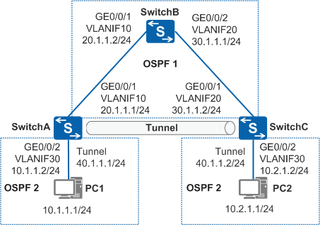
- SwitchA, SwitchB, and SwitchC communicate with each other through a public network. (The OSPF protocol is used in this example.)
- PC1 and PC2 run the IPv4 proprietary protocol and communicate with each other over the public network. Transmission of private data must be reliable.
PC1 uses SwitchA and PC2 uses SwitchC as a default gateway.
Configuration Roadmap
You can set up a directly connected GRE tunnel between SwitchA and SwitchC and configure OSPF on tunnel interfaces and interfaces connected to the private networks to allow PC1 to communicate with PC2. To monitor tunnel link status, enable Keepalive detection on tunnel interfaces on both ends of the GRE tunnel.
The configuration roadmap is as follows:
Configure an IGP (OSPF process 1 in this example) to implement interworking among devices.
Set up a GRE tunnel between devices connected to the PCs, enable Keepalive detection, and run an IGP (OSPF process 2 in this example) on the network segments connected to the PCs to transmit traffic between PC1 and PC2 over the GRE tunnel.
Procedure
- Configure an IP address for each physical interface.
# Configure SwitchA.
<HUAWEI> system-view
[HUAWEI] sysname SwitchA
[SwitchA] vlan batch 10 30
[SwitchA] interface gigabitethernet 0/0/1
[SwitchA-GigabitEthernet0/0/1] port link-type trunk
[SwitchA-GigabitEthernet0/0/1] port trunk allow-pass vlan 10
[SwitchA-GigabitEthernet0/0/1] quit
[SwitchA] interface gigabitethernet 0/0/2
[SwitchA-GigabitEthernet0/0/2] port link-type access
[SwitchA-GigabitEthernet0/0/2] port default vlan 30
[SwitchA-GigabitEthernet0/0/2] quit
[SwitchA] interface vlanif 10
[SwitchA-Vlanif10] ip address 20.1.1.1 24
[SwitchA-Vlanif10] quit
[SwitchA] interface vlanif 30
[SwitchA-Vlanif30] ip address 10.1.1.2 24
[SwitchA-Vlanif30] quit
# Configure SwitchB.
<HUAWEI> system-view
[HUAWEI] sysname SwitchB
[SwitchB] vlan batch 10 20
[SwitchB] interface gigabitethernet 0/0/1
[SwitchB-GigabitEthernet0/0/1] port link-type trunk
[SwitchB-GigabitEthernet0/0/1] port trunk allow-pass vlan 10
[SwitchB-GigabitEthernet0/0/1] quit
[SwitchB] interface gigabitethernet 0/0/2
[SwitchB-GigabitEthernet0/0/2] port link-type trunk
[SwitchB-GigabitEthernet0/0/2] port trunk allow-pass vlan 20
[SwitchB-GigabitEthernet0/0/2] quit
[SwitchB] interface vlanif 10
[SwitchB-Vlanif10] ip address 20.1.1.2 24
[SwitchB-Vlanif10] quit
[SwitchB] interface vlanif 20
[SwitchB-Vlanif20] ip address 30.1.1.1 24
[SwitchB-Vlanif20] quit
# Configure SwitchC.
<HUAWEI> system-view
[HUAWEI] sysname SwitchC
[SwitchC] vlan batch 20 30
[SwitchC] interface gigabitethernet 0/0/1
[SwitchC-GigabitEthernet0/0/1] port link-type trunk
[SwitchC-GigabitEthernet0/0/1] port trunk allow-pass vlan 20
[SwitchC-GigabitEthernet0/0/1] quit
[SwitchC] interface gigabitethernet 0/0/2
[SwitchC-GigabitEthernet0/0/2] port link-type access
[SwitchC-GigabitEthernet0/0/2] port default vlan 30
[SwitchC-GigabitEthernet0/0/2] quit
[SwitchC] interface vlanif 20
[SwitchC-Vlanif20] ip address 30.1.1.2 24
[SwitchC-Vlanif20] quit
[SwitchC] interface vlanif 30
[SwitchC-Vlanif30] ip address 10.2.1.2 24
[SwitchC-Vlanif30] quit
- Configure OSPF on the devices.
# Configure SwitchA.
[SwitchA] ospf 1
[SwitchA-ospf-1] area 0
[SwitchA-ospf-1-area-0.0.0.0] network 20.1.1.0 0.0.0.255
[SwitchA-ospf-1-area-0.0.0.0] quit
[SwitchA-ospf-1] quit
# Configure SwitchB.
[SwitchB] ospf 1
[SwitchB-ospf-1] area 0
[SwitchB-ospf-1-area-0.0.0.0] network 20.1.1.0 0.0.0.255
[SwitchB-ospf-1-area-0.0.0.0] network 30.1.1.0 0.0.0.255
[SwitchB-ospf-1-area-0.0.0.0] quit
[SwitchB-ospf-1] quit
# Configure SwitchC.
[SwitchC] ospf 1
[SwitchC-ospf-1] area 0
[SwitchC-ospf-1-area-0.0.0.0] network 30.1.1.0 0.0.0.255
[SwitchC-ospf-1-area-0.0.0.0] quit
[SwitchC-ospf-1] quit
# After the configuration is complete, run the display ip routing-table command on SwitchA and SwitchC. The command output shows that they have learned the OSPF route destined for the network segment of the peer.
- Configure a tunnel interface.
# Configure SwitchA.
[SwitchA] interface tunnel 1
[SwitchA-Tunnel1] tunnel-protocol gre
[SwitchA-Tunnel1] ip address 40.1.1.1 255.255.255.0
[SwitchA-Tunnel1] source 20.1.1.1
[SwitchA-Tunnel1] destination 30.1.1.2
[SwitchA-Tunnel1] keepalive
[SwitchA-Tunnel1] quit
# Configure SwitchC.
[SwitchC] interface tunnel 1
[SwitchC-Tunnel1] tunnel-protocol gre
[SwitchC-Tunnel1] ip address 40.1.1.2 255.255.255.0
[SwitchC-Tunnel1] source 30.1.1.2
[SwitchC-Tunnel1] destination 20.1.1.1
[SwitchC-Tunnel1] keepalive
[SwitchC-Tunnel1] quit
# After the configuration is complete, the tunnel interfaces turn Up and can ping each other.
# The command output on SwitchA is used as an example.
[SwitchA] ping -a 40.1.1.1 40.1.1.2
  PING 40.1.1.2: 56  data bytes, press CTRL_C to break
    Reply from 40.1.1.2: bytes=56 Sequence=1 ttl=255 time=1 ms
    Reply from 40.1.1.2: bytes=56 Sequence=2 ttl=255 time=1 ms
    Reply from 40.1.1.2: bytes=56 Sequence=3 ttl=255 time=1 ms
    Reply from 40.1.1.2: bytes=56 Sequence=4 ttl=255 time=1 ms
    Reply from 40.1.1.2: bytes=56 Sequence=5 ttl=255 time=1 ms

  --- 40.1.1.2 ping statistics ---
    5 packet(s) transmitted
    5 packet(s) received
    0.00% packet loss
    round-trip min/avg/max = 1/1/1 ms
# Run the display keepalive packets count command to check Keepalive packets statistics.
# The command output on SwitchA is used as an example.
[SwitchA] interface tunnel 1
[SwitchA-Tunnel1] display keepalive packets count
Send 10 keepalive packets to peers, Receive 10 keepalive response packets from peers
Receive 8 keepalive packets from peers, Send 8 keepalive response packets to peers.
[SwitchA-Tunnel1] quit
- Configure OSPF on tunnel interfaces.
# Configure SwitchA.
[SwitchA] ospf 2
[SwitchA-ospf-2] area 0
[SwitchA-ospf-2-area-0.0.0.0] network 40.1.1.0 0.0.0.255
[SwitchA-ospf-2-area-0.0.0.0] network 10.1.1.0 0.0.0.255
[SwitchA-ospf-2-area-0.0.0.0] quit
[SwitchA-ospf-2] quit
# Configure SwitchC.
[SwitchC] ospf 2
[SwitchC-ospf-2] area 0
[SwitchC-ospf-2-area-0.0.0.0] network 40.1.1.0 0.0.0.255
[SwitchC-ospf-2-area-0.0.0.0] network 10.2.1.0 0.0.0.255
[SwitchC-ospf-2-area-0.0.0.0] quit
[SwitchC-ospf-2] quit
- Verify the configuration.
# After the configuration is complete, run the display ip routing-table command on SwitchA and SwitchC. The routing table of each router contains the OSPF route from the tunnel interface to the user-side network segment of the peer. In addition, the next hop of the route to the destination physical interface (30.1.1.0/24) of the tunnel is not a tunnel interface.
# The command output on SwitchA is used as an example.
[SwitchA] display ip routing-table protocol ospf
Route Flags: R - relay, D - download to fib, T - to vpn-instance
------------------------------------------------------------------------------
Public routing table : OSPF
         Destinations : 2        Routes : 2

OSPF routing table status : <Active>
         Destinations : 2        Routes : 2

Destination/Mask    Proto   Pre  Cost      Flags NextHop         Interface

       10.2.1.0/24  OSPF    10   1563        D   40.1.1.2        Tunnel1
       30.1.1.0/24  OSPF    10   2           D   20.1.1.2        Vlanif10

OSPF routing table status : <Inactive>
         Destinations : 0        Routes : 0
# PC1 and PC2 can ping each other.
Configuration Files
SwitchA configuration file
#
sysname SwitchA
#
vlan batch 10 30
#
interface Vlanif10
 ip address 20.1.1.1 255.255.255.0
#
interface Vlanif30
 ip address 10.1.1.2 255.255.255.0
#
interface GigabitEthernet0/0/1
 port link-type trunk
 port trunk allow-pass vlan 10
#
interface GigabitEthernet0/0/2
 port link-type access
 port default vlan 30
#
interface Tunnel1
 ip address 40.1.1.1 255.255.255.0
 tunnel-protocol gre
 keepalive
 source 20.1.1.1
 destination 30.1.1.2
#
ospf 1
 area 0.0.0.0
  network 20.1.1.0 0.0.0.255
#
ospf 2
 area 0.0.0.0
  network 10.1.1.0 0.0.0.255
  network 40.1.1.0 0.0.0.255
#
return
SwitchB configuration file
#
sysname SwitchB
#
vlan batch 10 20
#
interface Vlanif10
 ip address 20.1.1.2 255.255.255.0
#
interface Vlanif20
 ip address 30.1.1.1 255.255.255.0
#
interface GigabitEthernet0/0/1
 port link-type trunk
 port trunk allow-pass vlan 10
#
interface GigabitEthernet0/0/2
 port link-type trunk
 port trunk allow-pass vlan 20
#
ospf 1
 area 0.0.0.0
  network 20.1.1.0 0.0.0.255
  network 30.1.1.0 0.0.0.255
#
return
SwitchC configuration file
#
sysname SwitchC
#
vlan batch 20 30
#
interface Vlanif20
 ip address 30.1.1.2 255.255.255.0
#
interface Vlanif30
 ip address 10.2.1.2 255.255.255.0
#
interface GigabitEthernet0/0/1
 port link-type trunk
 port trunk allow-pass vlan 20
#
interface GigabitEthernet0/0/2
 port link-type access
 port default vlan 30
#
interface Tunnel1
 ip address 40.1.1.2 255.255.255.0
 tunnel-protocol gre
 keepalive
 source 30.1.1.2
 destination 20.1.1.1
#
ospf 1
 area 0.0.0.0
  network 30.1.1.0 0.0.0.255
#
ospf 2
 area 0.0.0.0
  network 10.2.1.0 0.0.0.255
  network 40.1.1.0 0.0.0.255
#
return