Example for Enlarging the Operation Scope of a Network with a Hop Limit
Networking Requirements
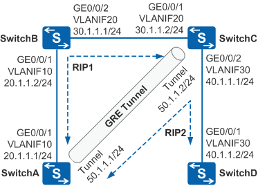
As shown in Figure 1, SwitchA, SwitchB, SwitchC, and SwitchD run RIP to implement public interworking. Data sent from SwitchA to SwitchD must pass through only one hop. That is, the route cost is 1. RIP is deployed without changing the network topology. There are two hops between SwitchA and SwitchD. To reduce a hop, you need to set up a GRE tunnel between SwitchA and SwitchC. Although the logical hop count is 1, there are two devices on the path from SwitchA to SwitchD. Therefore, the hop count allowed on a RIP network is increased.
Configuration Roadmap
The configuration roadmap is as follows:
Run RIP process 1 on SwitchA, SwitchB, and SwitchC to implement interworking among them.
Set up a GRE tunnel between SwitchA and SwitchC to hide SwitchB.
Run RIP process 2 on SwitchA, SwitchC, and SwitchD to forward packets over the GRE tunnel. The actual hop counts allowed on a RIP network is increased.
Procedure
- Configure an IP address for each physical interface.
# Configure SwitchA.
<HUAWEI> system-view
[HUAWEI] sysname SwitchA
[SwitchA] vlan batch 10
[SwitchA] interface gigabitethernet 0/0/1
[SwitchA-GigabitEthernet0/0/1] port link-type trunk
[SwitchA-GigabitEthernet0/0/1] port trunk allow-pass vlan 10
[SwitchA-GigabitEthernet0/0/1] quit
[SwitchA] interface vlanif 10
[SwitchA-Vlanif10] ip address 20.1.1.1 24
[SwitchA-Vlanif10] quit
# Configure SwitchB.
<HUAWEI> system-view
[HUAWEI] sysname SwitchB
[SwitchB] vlan batch 10 20
[SwitchB] interface gigabitethernet 0/0/1
[SwitchB-GigabitEthernet0/0/1] port link-type trunk
[SwitchB-GigabitEthernet0/0/1] port trunk allow-pass vlan 10
[SwitchB-GigabitEthernet0/0/1] quit
[SwitchB] interface gigabitethernet 0/0/2
[SwitchB-GigabitEthernet0/0/2] port link-type trunk
[SwitchB-GigabitEthernet0/0/2] port trunk allow-pass vlan 20
[SwitchB-GigabitEthernet0/0/2] quit
[SwitchB] interface vlanif 10
[SwitchB-Vlanif10] ip address 20.1.1.2 24
[SwitchB-Vlanif10] quit
[SwitchB] interface vlanif 20
[SwitchB-Vlanif20] ip address 30.1.1.1 24
[SwitchB-Vlanif20] quit
# Configure SwitchC.
<HUAWEI> system-view
[HUAWEI] sysname SwitchC
[SwitchC] vlan batch 20 30
[SwitchC] interface gigabitethernet 0/0/1
[SwitchC-GigabitEthernet0/0/1] port link-type trunk
[SwitchC-GigabitEthernet0/0/1] port trunk allow-pass vlan 20
[SwitchC-GigabitEthernet0/0/1] quit
[SwitchC] interface gigabitethernet 0/0/2
[SwitchC-GigabitEthernet0/0/2] port link-type trunk
[SwitchC-GigabitEthernet0/0/2] port trunk allow-pass vlan 30
[SwitchC-GigabitEthernet0/0/2] quit
[SwitchC] interface vlanif 20
[SwitchC-Vlanif20] ip address 30.1.1.2 24
[SwitchC-Vlanif20] quit
[SwitchC] interface vlanif 30
[SwitchC-Vlanif30] ip address 40.1.1.1 24
[SwitchC-Vlanif30] quit
# Configure SwitchD.
<HUAWEI> system-view
[HUAWEI] sysname SwitchD
[SwitchD] vlan batch 30
[SwitchD] interface gigabitethernet 0/0/1
[SwitchD-GigabitEthernet0/0/1] port link-type trunk
[SwitchD-GigabitEthernet0/0/1] port trunk allow-pass vlan 30
[SwitchD-GigabitEthernet0/0/1] quit
[SwitchD] interface vlanif 30
[SwitchD-Vlanif30] ip address 40.1.1.2 24
[SwitchD-Vlanif30] quit
- Run RIP process 1 on devices.
# Configure SwitchA.
[SwitchA] rip 1
[SwitchA-rip-1] version 2
[SwitchA-rip-1] network 20.0.0.0
[SwitchA-rip-1] quit
# Configure SwitchB.
[SwitchB] rip 1
[SwitchB-rip-1] version 2
[SwitchB-rip-1] network 20.0.0.0
[SwitchB-rip-1] network 30.0.0.0
[SwitchB-rip-1] quit
# Configure SwitchC.
[SwitchC] rip 1
[SwitchC-rip-1] version 2
[SwitchC-rip-1] network 30.0.0.0
[SwitchC-rip-1] quit
# After the configuration is complete, run the display ip routing-table command on SwitchA and SwitchC. The command output shows that they have learned the RIP route destined for the network segment of the peer.
- Configure a tunnel interface.
# Configure SwitchA.
[SwitchA] interface tunnel 1
[SwitchA-Tunnel1] tunnel-protocol gre
[SwitchA-Tunnel1] ip address 50.1.1.1 255.255.255.0
[SwitchA-Tunnel1] source 20.1.1.1
[SwitchA-Tunnel1] destination 30.1.1.2
[SwitchA-Tunnel1] quit
# Configure SwitchC.
[SwitchC] interface tunnel 1
[SwitchC-Tunnel1] tunnel-protocol gre
[SwitchC-Tunnel1] ip address 50.1.1.2 255.255.255.0
[SwitchC-Tunnel1] source 30.1.1.2
[SwitchC-Tunnel1] destination 20.1.1.1
[SwitchC-Tunnel1] quit
# After the configuration is complete, the tunnel interfaces turn Up and can ping each other.
# The command output on SwitchA is used as an example.
[SwitchA] ping -a 50.1.1.1 50.1.1.2 PING 50.1.1.2: 56 data bytes, press CTRL_C to break Reply from 50.1.1.2: bytes=56 Sequence=1 ttl=255 time=1 ms Reply from 50.1.1.2: bytes=56 Sequence=2 ttl=255 time=1 ms Reply from 50.1.1.2: bytes=56 Sequence=3 ttl=255 time=1 ms Reply from 50.1.1.2: bytes=56 Sequence=4 ttl=255 time=1 ms Reply from 50.1.1.2: bytes=56 Sequence=5 ttl=255 time=1 ms --- 50.1.1.2 ping statistics --- 5 packet(s) transmitted 5 packet(s) received 0.00% packet loss round-trip min/avg/max = 1/1/1 ms - Run RIP process 2 on tunnel interfaces.
# Configure SwitchA.
[SwitchA] rip 2
[SwitchA-rip-2] version 2
[SwitchA-rip-2] network 50.0.0.0
[SwitchA-rip-2] quit
# Configure SwitchC.
[SwitchC] rip 2
[SwitchC-rip-2] version 2
[SwitchC-rip-2] network 40.0.0.0
[SwitchC-rip-2] network 50.0.0.0
[SwitchC-rip-2] quit
# Configure SwitchD.
[SwitchD] rip 2
[SwitchD-rip-2] version 2
[SwitchD-rip-2] network 40.0.0.0
[SwitchD-rip-2] quit
- Verify the configuration.
# After the configuration is complete, run the display ip routing-table command on SwitchA and SwitchD. The command output shows that the cost of the route to the destination address of the peer device is 1.
# The command output on SwitchA is used as an example.
[SwitchA] display ip routing-table
Route Flags: R - relay, D - download to fib, T - to vpn-instance
------------------------------------------------------------------------------
Routing Tables: Public
         Destinations : 8        Routes : 8

Destination/Mask    Proto   Pre  Cost      Flags NextHop         Interface

       20.1.1.0/24  Direct  0    0           D  20.1.1.1        Vlanif10
       20.1.1.1/32  Direct  0    0           D  127.0.0.1       Vlanif10
       30.1.1.0/24  RIP     100  1           D  20.1.1.2        Vlanif10
       40.1.1.0/24  RIP     100  1           D  50.1.1.2        Tunnel1
       50.1.1.0/24  Direct  0    0           D  50.1.1.1        Tunnel1
       50.1.1.1/32  Direct  0    0           D  127.0.0.1       Tunnel1
      127.0.0.0/8   Direct  0    0           D  127.0.0.1       InLoopBack0
      127.0.0.1/32  Direct  0    0           D  127.0.0.1       InLoopBack0
Configuration Files
SwitchA configuration file
#
sysname SwitchA
#
vlan batch 10
#
interface Vlanif10
 ip address 20.1.1.1 255.255.255.0
#
interface GigabitEthernet0/0/1
 port link-type trunk
 port trunk allow-pass vlan 10
#
interface Tunnel1
 ip address 50.1.1.1 255.255.255.0
 tunnel-protocol gre
 source 20.1.1.1
 destination 30.1.1.2
#
rip 1
 version 2
 network 20.0.0.0
#
rip 2
 version 2
 network 50.0.0.0
#
return
SwitchB configuration file
#
sysname SwitchB
#
vlan batch 10 20
#
interface Vlanif10
 ip address 20.1.1.2 255.255.255.0
#
interface Vlanif20
 ip address 30.1.1.1 255.255.255.0
#
interface GigabitEthernet0/0/1
 port link-type trunk
 port trunk allow-pass vlan 10
#
interface GigabitEthernet0/0/2
 port link-type trunk
 port trunk allow-pass vlan 20
#
rip 1
 version 2
 network 20.0.0.0
 network 30.0.0.0
#
return
SwitchC configuration file
#
sysname SwitchC
#
vlan batch 20 30
#
interface Vlanif20
 ip address 30.1.1.2 255.255.255.0
#
interface Vlanif30
 ip address 40.1.1.1 255.255.255.0
#
interface GigabitEthernet0/0/1
 port link-type trunk
 port trunk allow-pass vlan 20
#
interface GigabitEthernet0/0/2
 port link-type trunk
 port trunk allow-pass vlan 30
#
interface Tunnel1
 ip address 50.1.1.2 255.255.255.0
 tunnel-protocol gre
 source 30.1.1.2
 destination 20.1.1.1
#
rip 1
 version 2
 network 30.0.0.0
#
rip 2
 version 2
 network 40.0.0.0
 network 50.0.0.0
#
return
SwitchD configuration file
#
sysname SwitchD
#
vlan batch 30
#
interface Vlanif30
 ip address 40.1.1.2 255.255.255.0
#
interface GigabitEthernet0/0/1
 port link-type trunk
 port trunk allow-pass vlan 30
#
rip 2
 version 2
 network 40.0.0.0
#
return