Example for Connecting a CE to a VPN Through a GRE Tunnel over a Public Network
Networking Requirements
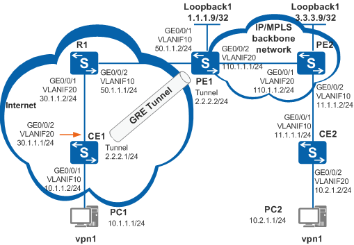
In Figure 1:
PE1 and PE2 reside on the MPLS backbone network.
R1 connects CE1 and PE1 over the public network.
CE2 is directly connected to PE2.
CE1 and CE2 reside on the same VPN and are reachable to each other.
PE1 is indirectly connected to CE1. Therefore, no VPN instance can be bound to the physical interface of PE1. A GRE tunnel is set up between CE1 and PE1 and this tunnel traverses the public network. On PE1, bind the GRE tunnel to a VPN to connect CE1 to the VPN using the GRE tunnel.
Configuration Roadmap
The configuration roadmap is as follows:
Run OSPF process 10 on PE1 and PE2 to implement interworking between them, and enable MPLS.
Run OSPF process 20 on CE1, R1, and PE1 to implement interworking among them.
Set up a GRE tunnel between CE1 and PE1.
Create vpn1 on PE1 and PE2. On PE1, bind vpn1 to the GRE tunnel interface. On PE2, bind vpn1 to the physical interface connected to CE2.
Configure Intermediate System to Intermediate System (IS-IS) on CE1 and CE2 to calculate routes between CE1, CE2 and their connected PEs.
Run BGP on the PEs to implement interworking between CE1 and CE2.
Procedure
- Configure an IP address for each interface.
# Configure CE1.
<HUAWEI> system-view
[HUAWEI] sysname CE1
[CE1] vlan batch 10 20
[CE1] interface gigabitethernet 0/0/1
[CE1-GigabitEthernet0/0/1] port link-type access
[CE1-GigabitEthernet0/0/1] port default vlan 10
[CE1-GigabitEthernet0/0/1] quit
[CE1] interface gigabitethernet 0/0/2
[CE1-GigabitEthernet0/0/2] port link-type trunk
[CE1-GigabitEthernet0/0/2] port trunk allow-pass vlan 20
[CE1-GigabitEthernet0/0/2] quit
[CE1] interface vlanif 10
[CE1-Vlanif10] ip address 10.1.1.2 24
[CE1-Vlanif10] quit
[CE1] interface vlanif 20
[CE1-Vlanif20] ip address 30.1.1.1 24
[CE1-Vlanif20] quit
# Configure R1.
<HUAWEI> system-view
[HUAWEI] sysname R1
[R1] vlan batch 10 20
[R1] interface gigabitethernet 0/0/1
[R1-GigabitEthernet0/0/1] port link-type trunk
[R1-GigabitEthernet0/0/1] port trunk allow-pass vlan 20
[R1-GigabitEthernet0/0/1] quit
[R1] interface gigabitethernet 0/0/2
[R1-GigabitEthernet0/0/2] port link-type trunk
[R1-GigabitEthernet0/0/2] port trunk allow-pass vlan 10
[R1-GigabitEthernet0/0/2] quit
[R1] interface vlanif 10
[R1-Vlanif10] ip address 50.1.1.1 24
[R1-Vlanif10] quit
[R1] interface vlanif 20
[R1-Vlanif20] ip address 30.1.1.2 24
[R1-Vlanif20] quit
# Configure PE1.
<HUAWEI> system-view
[HUAWEI] sysname PE1
[PE1] vlan batch 10 20
[PE1] interface gigabitethernet 0/0/1
[PE1-GigabitEthernet0/0/1] port link-type trunk
[PE1-GigabitEthernet0/0/1] port trunk allow-pass vlan 10
[PE1-GigabitEthernet0/0/1] quit
[PE1] interface gigabitethernet 0/0/2
[PE1-GigabitEthernet0/0/2] port link-type trunk
[PE1-GigabitEthernet0/0/2] port trunk allow-pass vlan 20
[PE1-GigabitEthernet0/0/2] quit
[PE1] interface vlanif 10
[PE1-Vlanif10] ip address 50.1.1.2 24
[PE1-Vlanif10] quit
[PE1] interface vlanif 20
[PE1-Vlanif20] ip address 110.1.1.1 24
[PE1-Vlanif20] quit
[PE1] interface loopback 1
[PE1-LoopBack1] ip address 1.1.1.9 32
[PE1-LoopBack1] quit
# Configure IP addresses for interfaces on PE2 except the interface to be bound to a VPN instance. This is because all configurations on this interface are deleted when bound to a VPN instance.
<HUAWEI> system-view
[HUAWEI] sysname PE2
[PE2] vlan batch 10 20
[PE2] interface gigabitethernet 0/0/1
[PE2-GigabitEthernet0/0/1] port link-type trunk
[PE2-GigabitEthernet0/0/1] port trunk allow-pass vlan 20
[PE2-GigabitEthernet0/0/1] quit
[PE2] interface gigabitethernet 0/0/2
[PE2-GigabitEthernet0/0/2] port link-type trunk
[PE2-GigabitEthernet0/0/2] port trunk allow-pass vlan 10
[PE2-GigabitEthernet0/0/2] quit
[PE2] interface vlanif 20
[PE2-Vlanif20] ip address 110.1.1.2 24
[PE2-Vlanif20] quit
[PE2] interface loopback 1
[PE2-LoopBack1] ip address 3.3.3.9 32
[PE2-LoopBack1] quit
# Configure CE2.
<HUAWEI> system-view
[HUAWEI] sysname CE2
[CE2] vlan batch 10 20
[CE2] interface gigabitethernet 0/0/1
[CE2-GigabitEthernet0/0/1] port link-type trunk
[CE2-GigabitEthernet0/0/1] port trunk allow-pass vlan 10
[CE2-GigabitEthernet0/0/1] quit
[CE2] interface gigabitethernet 0/0/2
[CE2-GigabitEthernet0/0/2] port link-type access
[CE2-GigabitEthernet0/0/2] port default vlan 20
[CE2-GigabitEthernet0/0/2] quit
[CE2] interface vlanif 10
[CE2-Vlanif10] ip address 11.1.1.1 24
[CE2-Vlanif10] quit
[CE2] interface vlanif 20
[CE2-Vlanif20] ip address 10.2.1.2 24
[CE2-Vlanif20] quit
- Configure routes between the PEs and enable Multiprotocol Label Switching (MPLS).
# On PE1, enable MPLS Label Distribution Protocol (MPLS LDP), and run OSPF process 10 to configure reachable routes between the PEs. Label switched paths (LSPs) are set up automatically.
[PE1] mpls lsr-id 1.1.1.9
[PE1] mpls
[PE1-mpls] lsp-trigger all
[PE1-mpls] quit
[PE1] mpls ldp
[PE1-mpls-ldp] quit
[PE1] ospf 10
[PE1-ospf-10] area 0
[PE1-ospf-10-area-0.0.0.0] network 1.1.1.9 0.0.0.0
[PE1-ospf-10-area-0.0.0.0] network 110.1.1.0 0.0.0.255
[PE1-ospf-10-area-0.0.0.0] quit
[PE1-ospf-10] quit
[PE1] interface vlanif 20
[PE1-Vlanif20] mpls
[PE1-Vlanif20] mpls ldp
[PE1-Vlanif20] quit
# On PE2, enable MPLS LDP, and run OSPF process 10 to configure reachable routes between the PEs. LSPs are set up automatically.
[PE2] mpls lsr-id 3.3.3.9
[PE2] mpls
[PE2-mpls] lsp-trigger all
[PE2-mpls] quit
[PE2] mpls ldp
[PE2-mpls-ldp] quit
[PE2] ospf 10
[PE2-ospf-10] area 0
[PE2-ospf-10-area-0.0.0.0] network 3.3.3.9 0.0.0.0
[PE2-ospf-10-area-0.0.0.0] network 110.1.1.0 0.0.0.255
[PE2-ospf-10-area-0.0.0.0] quit
[PE2-ospf-10] quit
[PE2] interface vlanif 20
[PE2-Vlanif20] mpls
[PE2-Vlanif20] mpls ldp
[PE2-Vlanif20] quit
- Create a VPN instance vpn1 on PE1 and bind vpn1 to the GRE tunnel.
[PE1] ip vpn-instance vpn1
[PE1-vpn-instance-vpn1] route-distinguisher 100:1
[PE1-vpn-instance-vpn1-af-ipv4] vpn-target 111:1 export-extcommunity
[PE1-vpn-instance-vpn1-af-ipv4] vpn-target 111:1 import-extcommunity
[PE1-vpn-instance-vpn1-af-ipv4] quit
[PE1-vpn-instance-vpn1] quit
[PE1] interface tunnel 1
[PE1-Tunnel1] ip binding vpn-instance vpn1
[PE1-Tunnel1] ip address 2.2.2.2 255.255.255.0
[PE1-Tunnel1] quit
- Create a VPN instance vpn1 on PE2 and bind vpn1 to a user-side interface.
[PE2] ip vpn-instance vpn1
[PE2-vpn-instance-vpn1] route-distinguisher 200:1
[PE2-vpn-instance-vpn1-af-ipv4] vpn-target 111:1 export-extcommunity
[PE2-vpn-instance-vpn1-af-ipv4] vpn-target 111:1 import-extcommunity
[PE2-vpn-instance-vpn1-af-ipv4] quit
[PE2-vpn-instance-vpn1] quit
[PE2] interface vlanif 10
[PE2-Vlanif10] ip binding vpn-instance vpn1
[PE2-Vlanif10] ip address 11.1.1.2 255.255.255.0
[PE2-Vlanif10] quit
- Configure GRE tunnel interfaces.
# Configure CE1.
[CE1] interface tunnel 1
[CE1-Tunnel1] tunnel-protocol gre
[CE1-Tunnel1] source 30.1.1.1
[CE1-Tunnel1] destination 50.1.1.2
[CE1-Tunnel1] ip address 2.2.2.1 24
[CE1-Tunnel1] quit
# Configure PE1.
[PE1] interface tunnel 1
[PE1-Tunnel1] tunnel-protocol gre
[PE1-Tunnel1] source 50.1.1.2
[PE1-Tunnel1] destination 30.1.1.1
[PE1-Tunnel1] quit
- Configure OSPF on CE1, R1, and PE1.
# Configure CE1.
[CE1] ospf 20
[CE1-ospf-20] area 0
[CE1-ospf-20-area-0.0.0.0] network 30.1.1.0 0.0.0.255
[CE1-ospf-20-area-0.0.0.0] quit
[CE1-ospf-20] quit
# Configure R1.
[R1] ospf 20
[R1-ospf-20] area 0
[R1-ospf-20-area-0.0.0.0] network 30.1.1.0 0.0.0.255
[R1-ospf-20-area-0.0.0.0] network 50.1.1.0 0.0.0.255
[R1-ospf-20-area-0.0.0.0] quit
[R1-ospf-20] quit
# Configure PE1.
[PE1] ospf 20
[PE1-ospf-20] area 0
[PE1-ospf-20-area-0.0.0.0] network 50.1.1.0 0.0.0.255
[PE1-ospf-20-area-0.0.0.0] quit
[PE1-ospf-20] quit
- Configure IS-IS on CE1 and PE1 to calculate routes between them.
# Configure CE1.
[CE1] isis 50
[CE1-isis-50] network-entity 50.0000.0000.0001.00
[CE1-isis-50] quit
[CE1] interface vlanif 10
[CE1-Vlanif10] isis enable 50
[CE1-Vlanif10] quit
[CE1] interface tunnel 1
[CE1-Tunnel1] isis enable 50
[CE1-Tunnel1] quit
# Configure PE1.
[PE1] isis 50 vpn-instance vpn1
[PE1-isis-50] network-entity 50.0000.0000.0002.00
[PE1-isis-50] quit
[PE1] interface tunnel 1
[PE1-Tunnel1] isis enable 50
[PE1-Tunnel1] quit
- Configure IS-IS on CE2 and PE2 to calculate routes between them.
# Configure CE2.
[CE2] isis 50
[CE2-isis-50] network-entity 50.0000.0000.0004.00
[CE2-isis-50] quit
[CE2] interface vlanif 10
[CE2-Vlanif10] isis enable 50
[CE2-Vlanif10] quit
[CE2] interface vlanif 20
[CE2-Vlanif20] isis enable 50
[CE2-Vlanif20] quit
# Configure PE2.
[PE2] isis 50 vpn-instance vpn1
[PE2-isis-50] network-entity 50.0000.0000.0003.00
[PE2-isis-50] quit
[PE2] interface vlanif 10
[PE2-Vlanif10] isis enable 50
[PE2-Vlanif10] quit
- Set up a Multiprotocol Interior Border Gateway Protocol (MP-IBGP) peer relationship between the PEs.
# On PE1, configure an Interior Border Gateway Protocol (IBGP) peer relationship with PE2 using a loopback interface to exchange VPN IPv4 route information.
[PE1] bgp 100
[PE1-bgp] peer 3.3.3.9 as-number 100
[PE1-bgp] peer 3.3.3.9 connect-interface loopback 1
[PE1-bgp] ipv4-family vpnv4
[PE1-bgp-af-vpnv4] peer 3.3.3.9 enable
[PE1-bgp-af-vpnv4] quit
# Import IS-IS routes to vpn1.
[PE1-bgp] ipv4-family vpn-instance vpn1
[PE1-bgp-vpn1] import-route isis 50
[PE1-bgp-vpn1] quit
[PE1-bgp] quit
# On PE2, configure an IBGP peer relationship with PE1 using a loopback interface to exchange VPN IPv4 route information.
[PE2] bgp 100
[PE2-bgp] peer 1.1.1.9 as-number 100
[PE2-bgp] peer 1.1.1.9 connect-interface loopback 1
[PE2-bgp] ipv4-family vpnv4
[PE2-bgp-af-vpnv4] peer 1.1.1.9 enable
[PE2-bgp-af-vpnv4] quit
# Import IS-IS routes to vpn1.
[PE2-bgp] ipv4-family vpn-instance vpn1
[PE2-bgp-vpn1] import-route isis 50
[PE2-bgp-vpn1] quit
[PE2-bgp] quit
- Import BGP routes to the IS-IS routing table.
# Configure PE1.
[PE1] isis 50
[PE1-isis-50] import-route bgp
[PE1-isis-50] quit
# Configure PE2.
[PE2] isis 50
[PE2-isis-50] import-route bgp
[PE2-isis-50] quit
- Verify the configuration.
# After the configuration is complete, CE1 and CE2 have reachable routes to each other. The command output on CE1 is used as an example.
[CE1] display isis peer

                         Peer information for ISIS(50)

  System Id     Interface          Circuit Id       State HoldTime Type     PRI
-------------------------------------------------------------------------------
0000.0000.0002  Tun1               0000000001        Up   26s      L1L2     --

Total Peer(s): 1
[CE1] display ip routing-table 10.2.1.0 Route Flags: R - relay, D - download to fib, T - to vpn-instance ------------------------------------------------------------------------------ Routing Table : Public Summary Count : 1 Destination/Mask Proto Pre Cost Flags NextHop Interface 10.2.1.0/24 ISIS-L2 15 74 D 2.2.2.2 Tunnel1
Configuration Files
CE1 configuration file
#
sysname CE1
#
vlan batch 10 20
#
isis 50
 network-entity 50.0000.0000.0001.00
#
interface Vlanif10
 ip address 10.1.1.2 255.255.255.0
 isis enable 50
#
interface Vlanif20
 ip address 30.1.1.1 255.255.255.0
#
interface GigabitEthernet0/0/1
 port link-type access
 port default vlan 10
#
interface GigabitEthernet0/0/2
 port link-type trunk
 port trunk allow-pass vlan 20
#
interface Tunnel1
 ip address 2.2.2.1 255.255.255.0
 tunnel-protocol gre
 source 30.1.1.1
 destination 50.1.1.2
 isis enable 50
#
ospf 20
 area 0.0.0.0
  network 30.1.1.0 0.0.0.255
#
return
R1 configuration file
#
sysname R1
#
vlan batch 10 20
#
interface Vlanif10
 ip address 50.1.1.1 255.255.255.0
#
interface Vlanif20
 ip address 30.1.1.2 255.255.255.0
#
interface GigabitEthernet0/0/1
 port link-type trunk
 port trunk allow-pass vlan 20
#
interface GigabitEthernet0/0/2
 port link-type trunk
 port trunk allow-pass vlan 10
#
ospf 20
 area 0.0.0.0
  network 30.1.1.0 0.0.0.255
  network 50.1.1.0 0.0.0.255
#
return
PE1 configuration file
#
sysname PE1
#
vlan batch 10 20
#
ip vpn-instance vpn1
 ipv4-family
  route-distinguisher 100:1
  vpn-target 111:1 export-extcommunity
  vpn-target 111:1 import-extcommunity
#
mpls lsr-id 1.1.1.9
mpls
 lsp-trigger all
#
mpls ldp
#
isis 50 vpn-instance vpn1
 network-entity 50.0000.0000.0002.00
 import-route bgp
#
interface Vlanif10
 ip address 50.1.1.2 255.255.255.0
#
interface Vlanif20
 ip address 110.1.1.1 255.255.255.0
 mpls
 mpls ldp
#
interface GigabitEthernet0/0/1
 port link-type trunk
 port trunk allow-pass vlan 10
#
interface GigabitEthernet0/0/2
 port link-type trunk
 port trunk allow-pass vlan 20
#
interface LoopBack1
 ip address 1.1.1.9 255.255.255.255
#
interface Tunnel1
 ip binding vpn-instance vpn1
 ip address 2.2.2.2 255.255.255.0
 tunnel-protocol gre
 source 50.1.1.2
 destination 30.1.1.1
 isis enable 50
#
bgp 100
 peer 3.3.3.9 as-number 100
 peer 3.3.3.9 connect-interface LoopBack1
 #
 ipv4-family unicast
  undo synchronization
  peer 3.3.3.9 enable
 #
 ipv4-family vpnv4
  policy vpn-target
  peer 3.3.3.9 enable
 #
 ipv4-family vpn-instance vpn1
  import-route isis 50
#
ospf 10
 area 0.0.0.0
  network 1.1.1.9 0.0.0.0
  network 110.1.1.0 0.0.0.255
#
ospf 20
 area 0.0.0.0
  network 50.1.1.0 0.0.0.255
#
return
PE2 configuration file
#
sysname PE2
#
vlan batch 10 20
#
ip vpn-instance vpn1
 ipv4-family
  route-distinguisher 200:1
  vpn-target 111:1 export-extcommunity
  vpn-target 111:1 import-extcommunity
#
mpls lsr-id 3.3.3.9
mpls
 lsp-trigger all
#
mpls ldp
#
isis 50 vpn-instance vpn1
 network-entity 50.0000.0000.0003.00
 import-route bgp
#
interface Vlanif10
 ip binding vpn-instance vpn1
 ip address 11.1.1.2 255.255.255.0
 isis enable 50
#
interface Vlanif20
 ip address 110.1.1.2 255.255.255.0
 mpls
 mpls ldp
#
interface GigabitEthernet0/0/1
 port link-type trunk
 port trunk allow-pass vlan 20
#
interface GigabitEthernet0/0/2
 port link-type trunk
 port trunk allow-pass vlan 10
#
interface LoopBack1
 ip address 3.3.3.9 255.255.255.255
#
bgp 100
 peer 1.1.1.9 as-number 100
 peer 1.1.1.9 connect-interface LoopBack1
 #
 ipv4-family unicast
  undo synchronization
  peer 1.1.1.9 enable
 #
 ipv4-family vpnv4
  policy vpn-target
  peer 1.1.1.9 enable
 #
 ipv4-family vpn-instance vpn1
  import-route isis 50
#
ospf 10
 area 0.0.0.0
  network 3.3.3.9 0.0.0.0
  network 110.1.1.0 0.0.0.255
#
return
CE2 configuration file
#
sysname CE2
#
vlan batch 10 20
#
isis 50
 network-entity 50.0000.0000.0004.00
#
interface Vlanif10
 ip address 11.1.1.1 255.255.255.0
 isis enable 50
#
interface Vlanif20
 ip address 10.2.1.2 255.255.255.0
 isis enable 50
#
interface GigabitEthernet0/0/1
 port link-type trunk
 port trunk allow-pass vlan 10
#
interface GigabitEthernet0/0/2
 port link-type access
 port default vlan 20
#
return