Example for Configuring IGMP SSM Mapping
Networking Requirements
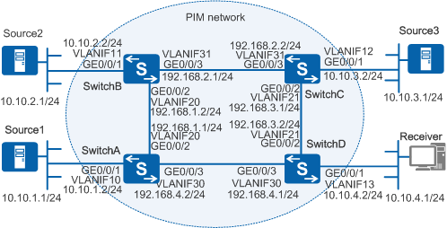
As shown in Figure 1, the network runs Protocol Independent Multicast - Sparse Mode (PIM-SM) and uses the source-specific multicast (SSM) model to provide multicast services to group members. The switch interface VLANIF13 connected to the network segment of Receiver runs IGMPv3. Receiver runs IGMPv2 and does not support IGMPv3; therefore, Receiver cannot specify desired multicast sources when it joins a group. The SSM group address range on the network is 232.1.1.0/24. Source1, Source2, and Source3 all send multicast data to the multicast groups in this range.
Receiver needs to obtain the SSM service and wants to receive only multicast data sent from Source1 and Source3.

In this scenario, to avoid loops, ensure that all connected interfaces have STP disabled and connected interfaces are removed from VLAN 1. If STP is enabled and VLANIF interfaces of switches are used to construct a Layer 3 ring network, an interface on the network will be blocked. As a result, Layer 3 services on the network cannot run normally.
Configuration Roadmap
Based on the receiver's requirement, you need to configure IGMP SSM mapping on SwitchD. The configuration roadmap is as follows:
To ensure that data sent from the multicast sources can be correctly forwarded to the network segment of Receiver, configure a unicast routing protocol on the network to implement IP interworking. Multicast routing protocols are dependent on unicast routing protocols.
To enable the switches to forward multicast data to Receiver, configure basic multicast functions on switches.
To allow Receiver to receive data from specified multicast sources, enable IGMP SSM mapping and configure mapping rules on SwitchD.
Procedure
- Configure IP addresses for interfaces and configure a unicast routing protocol on each switch.
# Configure IP addresses and masks for switch interfaces according to Figure 1. Configure Open Shortest Path First (OSPF) on the switches to implement IP interworking and dynamic route update. The configurations of SwitchB, SwitchC, and SwitchD are similar to the configuration of SwitchA, and are not mentioned here. See Configuration Files.
<HUAWEI> system-view
[HUAWEI] sysname SwitchA
[SwitchA] vlan batch 10 20 30
[SwitchA] interface gigabitethernet 0/0/1
[SwitchA-GigabitEthernet0/0/1] port link-type hybrid
[SwitchA-GigabitEthernet0/0/1] port hybrid untagged vlan 10
[SwitchA-GigabitEthernet0/0/1] port hybrid pvid vlan 10
[SwitchA-GigabitEthernet0/0/1] quit
[SwitchA] interface gigabitethernet 0/0/2
[SwitchA-GigabitEthernet0/0/2] port link-type trunk
[SwitchA-GigabitEthernet0/0/2] port trunk allow-pass vlan 20
[SwitchA-GigabitEthernet0/0/2] quit
[SwitchA] interface gigabitethernet 0/0/3
[SwitchA-GigabitEthernet0/0/3] port link-type trunk
[SwitchA-GigabitEthernet0/0/3] port trunk allow-pass vlan 30
[SwitchA-GigabitEthernet0/0/3] quit
[SwitchA] interface vlanif 10
[SwitchA-Vlanif10] ip address 10.10.1.2 24
[SwitchA-Vlanif10] quit
[SwitchA] interface vlanif 20
[SwitchA-Vlanif20] ip address 192.168.1.1 24
[SwitchA-Vlanif20] quit
[SwitchA] interface vlanif 30
[SwitchA-Vlanif30] ip address 192.168.4.2 24
[SwitchA-Vlanif30] quit
[SwitchA] ospf
[SwitchA-ospf-1] area 0
[SwitchA-ospf-1-area-0.0.0.0] network 10.10.1.0 0.0.0.255
[SwitchA-ospf-1-area-0.0.0.0] network 192.168.1.0 0.0.0.255
[SwitchA-ospf-1-area-0.0.0.0] network 192.168.4.0 0.0.0.255
[SwitchA-ospf-1-area-0.0.0.0] quit
[SwitchA-ospf-1] quit
- Enable IP multicast routing on all the switches and enable PIM-SM on all interfaces.
# Enable IP multicast routing on SwitchA and enable PIM-SM on all its interfaces. The configurations of SwitchB, SwitchC, and SwitchD are similar to the configuration of SwitchA, and are not mentioned here. See Configuration Files.
[SwitchA] multicast routing-enable
[SwitchA] interface vlanif 10
[SwitchA-Vlanif10] pim sm
[SwitchA-Vlanif10] quit
[SwitchA] interface vlanif 20
[SwitchA-Vlanif20] pim sm
[SwitchA-Vlanif20] quit
[SwitchA] interface vlanif 30
[SwitchA-Vlanif30] pim sm
[SwitchA-Vlanif30] quit
- # Configure a candidate bootstrap router (C-BSR) and a candidate rendezvous point (C-RP).
# Configure VLANIF30 as the C-BSR and C-RP on SwitchD.
[SwitchD] pim
[SwitchD-pim] c-bsr vlanif 30
[SwitchD-pim] c-rp vlanif 30
[SwitchD-pim] quit
- Enable IGMP on the interface of SwitchD connected to Receiver and set the IGMP version to IGMPv3.
# Enable IGMP on VLANIF13 of SwitchD and set the IGMP version to IGMPv3.
[SwitchD] interface vlanif 13
[SwitchD-Vlanif13] igmp enable
[SwitchD-Vlanif13] igmp version 3
[SwitchD-Vlanif13] quit
- Enable IGMP SSM mapping on the interface connected to Receiver.
# Enable SSM mapping on VLANIF13 of SwitchD.
[SwitchD] interface vlanif 13
[SwitchD-Vlanif13] igmp ssm-mapping enable
[SwitchD-Vlanif13] quit
- Configure the SSM group address range on all switches.
# Set the SSM group address range to 232.1.1.0/24 on SwitchA. The configurations of SwitchB, SwitchC, and SwitchD are similar to the configuration of SwitchA, and are not mentioned here. See Configuration Files.
[SwitchA] acl number 2000
[SwitchA-acl-basic-2000] rule permit source 232.1.1.0 0.0.0.255
[SwitchA-acl-basic-2000] quit
[SwitchA] pim
[SwitchA-pim] ssm-policy 2000
[SwitchA-pim] quit
- Configure IGMP SSM mapping rules on SwitchD.
# On SwitchD, map the multicast groups in the range of 232.1.1.0/24 to Source1 and Source3.
[SwitchD] igmp
[SwitchD-igmp] ssm-mapping 232.1.1.0 24 10.10.1.1
[SwitchD-igmp] ssm-mapping 232.1.1.0 24 10.10.3.1
[SwitchD-igmp] quit
- Verify the configuration.
# Run the display igmp ssm-mapping group command on SwitchD to view the mappings between multicast sources and multicast groups.
[SwitchD] display igmp ssm-mapping group
IGMP SSM-Mapping conversion table of VPN-Instance: public net
 Total 2 entries    2 entries matched

 00001. (10.10.1.1, 232.1.1.0/24)

 00002. (10.10.3.1, 232.1.1.0/24)

 Total 2 entries matched
The preceding information shows that multicast groups in the range of 232.1.1.0/24 are mapped to Source1 and Source3.
# Run the display igmp group ssm-mapping command on SwitchD to view information about the group address used in SSM mapping. The command output is as follows:
[SwitchD] display igmp group ssm-mapping IGMP SSM mapping interface group report information of VPN-Instance: public net Limited entry of this VPN-Instance: - Vlanif13 (10.10.4.2): Total 1 IGMP SSM-Mapping Group reported Group Address Last Reporter Uptime Expires 232.1.1.1 10.10.4.1 00:01:44 00:00:26[SwitchD] display igmp group ssm-mapping verbose Interface group report information of VPN-Instance: public net Limited entry of this VPN-Instance: - Vlanif13 (10.10.4.2): Total entry on this interface: 1 Limited entry on this interface: - Total 1 IGMP SSM-Mapping Group reported Group: 232.1.1.1 Uptime: 00:01:52 Expires: 00:00:18 Last reporter: 10.10.4.1 Last-member-query-counter: 0 Last-member-query-timer-expiry: off Group mode: exclude Version1-host-present-timer-expiry: off Version2-host-present-timer-expiry: 00:01:55The preceding information shows that Receiver has joined group 232.1.1.1.
# Run the display pim routing-table command on SwitchD to view the PIM-SM multicast routing table. The command output is as follows:
[SwitchD] display pim routing-table
VPN-Instance: public net
 Total 2 (S, G) entries
 (10.10.1.1, 232.1.1.1)
     Protocol: pim-ssm, Flag: SG_RCVR
     UpTime: 00:19:40
     Upstream interface: Vlanif30
         Upstream neighbor: 192.168.4.2
         RPF prime neighbor: 192.168.4.2
     Downstream interface(s) information:
     Total number of downstreams: 1
         1: Vlanif13
             Protocol: ssm-map, UpTime: 00:19:40, Expires: -

 (10.10.3.1, 232.1.1.1)
     Protocol: pim-ssm, Flag: SG_RCVR
     UpTime: 00:19:40
     Upstream interface: Vlanif21
         Upstream neighbor: 192.168.3.1
         RPF prime neighbor: 192.168.3.1
     Downstream interface(s) information:
     Total number of downstreams: 1
         1: Vlanif13
             Protocol: ssm-map, UpTime: 00:19:40, Expires: -
You can see that multicast sources 10.10.1.1 and 10.10.3.1 send data to group 232.1.1.1, and the data can be forwarded to Receiver through interfaces VLANIF30 and VLANIF21.
Configuration Files
SwitchA configuration file
#
sysname SwitchA
#
vlan batch 10 20 30
#
multicast routing-enable
#
acl number 2000
 rule 5 permit source 232.1.1.0 0.0.0.255
#
interface Vlanif10
 ip address 10.10.1.2 255.255.255.0
 pim sm
#
interface Vlanif20
 ip address 192.168.1.1 255.255.255.0
 pim sm
#
interface Vlanif30
 ip address 192.168.4.2 255.255.255.0
 pim sm
#
interface GigabitEthernet0/0/1
 port link-type hybrid
 port hybrid pvid vlan 10
 port hybrid untagged vlan 10
#
interface GigabitEthernet0/0/2
 port link-type trunk
 port trunk allow-pass vlan 20
#
interface GigabitEthernet0/0/3
 port link-type trunk
 port trunk allow-pass vlan 30
#
ospf 1
 area 0.0.0.0
  network 10.10.1.0 0.0.0.255
  network 192.168.1.0 0.0.0.255
  network 192.168.4.0 0.0.0.255
#
pim
 ssm-policy 2000
#
return
SwitchB configuration file
#
sysname SwitchB
#
vlan batch 11 20 31
#
multicast routing-enable
#
acl number 2000
 rule 5 permit source 232.1.1.0 0.0.0.255
#
interface Vlanif11
 ip address 10.10.2.2 255.255.255.0
 pim sm
#
interface Vlanif20
 ip address 192.168.1.2 255.255.255.0
 pim sm
#
interface Vlanif31
 ip address 192.168.2.1 255.255.255.0
 pim sm
#
interface GigabitEthernet0/0/1
 port link-type hybrid
 port hybrid pvid vlan 11
 port hybrid untagged vlan 11
#
interface GigabitEthernet0/0/2
 port link-type trunk
 port trunk allow-pass vlan 20
#
interface GigabitEthernet0/0/3
 port link-type trunk
 port trunk allow-pass vlan 31
#
ospf 1
 area 0.0.0.0
  network 10.10.2.0 0.0.0.255
  network 192.168.1.0 0.0.0.255
  network 192.168.2.0 0.0.0.255
#
pim
 ssm-policy 2000
#
return
SwitchC configuration file
#
sysname SwitchC
#
vlan batch 12 21 31
#
multicast routing-enable
#
acl number 2000
 rule 5 permit source 232.1.1.0 0.0.0.255
#
interface Vlanif12
 ip address 10.10.3.2 255.255.255.0
 pim sm
#
interface Vlanif21
 ip address 192.168.3.1 255.255.255.0
 pim sm
#
interface Vlanif31
 ip address 192.168.2.2 255.255.255.0
 pim sm
#
interface GigabitEthernet0/0/1
 port link-type hybrid
 port hybrid pvid vlan 12
 port hybrid untagged vlan 12
#
interface GigabitEthernet0/0/2
 port link-type trunk
 port trunk allow-pass vlan 21
#
interface GigabitEthernet0/0/3
 port link-type trunk
 port trunk allow-pass vlan 31
#
ospf 1
 area 0.0.0.0
  network 10.10.3.0 0.0.0.255
  network 192.168.2.0 0.0.0.255
  network 192.168.3.0 0.0.0.255
#
pim
 ssm-policy 2000
#
return
SwitchD configuration file
#
sysname SwitchD
#
vlan batch 13 21 30
#
multicast routing-enable
#
acl number 2000
 rule 5 permit source 232.1.1.0 0.0.0.255
#
interface Vlanif13
 ip address 10.10.4.2 255.255.255.0
 pim sm
 igmp enable
 igmp version 3
 igmp ssm-mapping enable
#
interface Vlanif21
 ip address 192.168.3.2 255.255.255.0
 pim sm
#
interface Vlanif30
 ip address 192.168.4.1 255.255.255.0
 pim sm
#
interface GigabitEthernet0/0/1
 port link-type hybrid
 port hybrid pvid vlan 13
 port hybrid untagged vlan 13
#
interface GigabitEthernet0/0/2
 port link-type trunk
 port trunk allow-pass vlan 21
#
interface GigabitEthernet0/0/3
 port link-type trunk
 port trunk allow-pass vlan 30
#
ospf 1
 area 0.0.0.0
  network 10.10.4.0 0.0.0.255
  network 192.168.3.0 0.0.0.255
  network 192.168.4.0 0.0.0.255
#
igmp
 ssm-mapping 232.1.1.0 255.255.255.0 10.10.1.1
 ssm-mapping 232.1.1.0 255.255.255.0 10.10.3.1
#
pim
 c-bsr Vlanif30
 c-rp Vlanif30
 ssm-policy 2000
#
return