Example for Configuring IGMP Limit
Networking Requirements
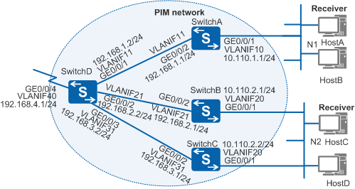
In Figure 1, a large number of receiver hosts on the network receive video streams in multicast mode. During peak usage periods, many users stream videos at the same time, consuming a large amount of bandwidth. As a result, performance of network devices degrades, and multicast data cannot be sent to user hosts in a stable manner.
To solve this problem, you can configure an IGMP limit to restrict the number of videos users are streaming. When the limit is reached, users cannot start streaming new video. This ensures that the current videos the users are streaming are delivered with a high quality. HostA connected to SwitchA frequently requests high-quality video streams of group 225.1.1.3.

In this scenario, to avoid loops, ensure that all connected interfaces have STP disabled and connected interfaces are removed from VLAN 1. If STP is enabled and VLANIF interfaces of switches are used to construct a Layer 3 ring network, an interface on the network will be blocked. As a result, Layer 3 services on the network cannot run normally.
Configuration Roadmap
To meet the preceding requirements, you need to configure static multicast group 225.1.1.3 on SwitchA's interface connected to the network segment of HostA, and configure an IGMP limit to restrict the number of group memberships on the switches. The configuration roadmap is as follows:
To ensure that data sent from multicast sources can be correctly forwarded to the user network segments, configure a unicast routing protocol on the network to implement IP interworking. Multicast routing protocols are dependent on unicast routing protocols.
To enable the switches to forward video streams to the hosts in multicast mode, configure basic multicast functions on the switches.
To allow HostA to receive high-quality video streams of group 225.1.1.3 any time, configure static group 225.1.1.3 on SwitchA's interface connected to the network segment of HostA.
To control the number of videos that users can stream, configure an IGMP limit on the switches. The IGMP limit does not affect the static multicast group configured on the interface and can ensure video quality for this group.
Procedure
- Configure IP addresses for interfaces and configure a unicast routing protocol on each switch.
# Configure IP addresses and masks for switch interfaces according to Figure 1. Configure Open Shortest Path First (OSPF) on the switches to implement IP interworking and dynamic route update. The configurations of SwitchB, SwitchC, and SwitchD are similar to the configuration of SwitchA, and are not mentioned here. See Configuration Files.
<HUAWEI> system-view
[HUAWEI] sysname SwitchA
[SwitchA] vlan batch 10 11
[SwitchA] interface gigabitethernet 0/0/1
[SwitchA-GigabitEthernet0/0/1] port link-type hybrid
[SwitchA-GigabitEthernet0/0/1] port hybrid untagged vlan 10
[SwitchA-GigabitEthernet0/0/1] port hybrid pvid vlan 10
[SwitchA-GigabitEthernet0/0/1] quit
[SwitchA] interface gigabitethernet 0/0/2
[SwitchA-GigabitEthernet0/0/2] port link-type trunk
[SwitchA-GigabitEthernet0/0/2] port trunk allow-pass vlan 11
[SwitchA-GigabitEthernet0/0/2] quit
[SwitchA] interface vlanif 10
[SwitchA-Vlanif10] ip address 10.110.1.1 24
[SwitchA-Vlanif10] quit
[SwitchA] interface vlanif 11
[SwitchA-Vlanif11] ip address 192.168.1.1 24
[SwitchA-Vlanif11] quit
[SwitchA] ospf
[SwitchA-ospf-1] area 0
[SwitchA-ospf-1-area-0.0.0.0] network 10.110.1.0 0.0.0.255
[SwitchA-ospf-1-area-0.0.0.0] network 192.168.1.0 0.0.0.255
[SwitchA-ospf-1-area-0.0.0.0] quit
[SwitchA-ospf-1] quit
- Enable IP multicast routing and Protocol Independent Multicast - Sparse Mode (PIM-SM).
# Enable IP multicast routing on SwitchA and enable PIM-SM on all its interfaces. The configurations of SwitchB, SwitchC, and SwitchD are similar to the configuration of SwitchA, and are not mentioned here. See Configuration Files.
[SwitchA] multicast routing-enable
[SwitchA] interface vlanif 10
[SwitchA-Vlanif10] pim sm
[SwitchA-Vlanif10] quit
[SwitchA] interface vlanif 11
[SwitchA-Vlanif11] pim sm
[SwitchA-Vlanif11] quit
- Configure a static rendezvous point (RP).
# Configure a static RP on SwitchA. Specify the IP address of VLANIF40 on SwitchD as the static RP address. The configurations of SwitchB, SwitchC, and SwitchD are similar to the configuration of SwitchA, and are not mentioned here. See Configuration Files.
[SwitchA] pim
[SwitchA-pim] static-rp 192.168.4.1
[SwitchA-pim] quit
- Enable IGMP on the interfaces connected to the user network segments.
# Enable IGMP on VLANIF10 of SwitchA. The configurations of SwitchB and SwitchC are similar to the configuration of SwitchA, and are not mentioned here. See Configuration Files.
[SwitchA] interface vlanif 10
[SwitchA-Vlanif10] igmp enable
[SwitchA-Vlanif10] quit
- Configure a static multicast group.
# Statically bind VLANIF10 of SwitchA to multicast group 225.1.1.3, so that HostA connected to VLANIF10 can receive stable multicast data of this group.
[SwitchA] interface vlanif 10
[SwitchA-Vlanif10] igmp static-group 225.1.1.3
[SwitchA-Vlanif10] quit
- Set the maximum number of IGMP entries on last-hop switches.
# Set the maximum number of IGMP entries on SwitchA to 50.
[SwitchA] igmp global limit 50# Set the maximum number of IGMP entries on VLANIF10 to 30.
[SwitchA] interface vlanif 10
[SwitchA-Vlanif10] igmp limit 30
[SwitchA-Vlanif10] quit
# The configurations of SwitchB and SwitchC are similar to the configuration of SwitchA, and are not mentioned here. See Configuration Files.
- Verify the configuration.
# Run the display igmp interface command to check the IGMP configuration and running status on switch interfaces. The IGMP command output on VLANIF10 of SwitchA is as follows:
[SwitchA] display igmp interface vlanif 10
Interface information of VPN-Instance: public net
 Vlanif10(10.110.1.1):
  IGMP is enabled
  Current IGMP version is 2
  IGMP state: up
  IGMP group policy: none
  IGMP limit: 30
  Value of query interval for IGMP (negotiated): -
  Value of query interval for IGMP (configured): 60 s
  Value of other querier timeout for IGMP: 0 s
  Value of maximum query response time for IGMP: 10 s
  Querier for IGMP: 10.110.1.1 (this router)
 Total 1 IGMP Group reported
You can see that a maximum of 30 IGMP group memberships can be created on VLANIF10 of SwitchA.
Configuration Files
SwitchA configuration file
#
sysname SwitchA
#
vlan batch 10 to 11
#
igmp global limit 50
#
multicast routing-enable
#
interface Vlanif10
 ip address 10.110.1.1 255.255.255.0
 pim sm
 igmp enable
 igmp limit 30
 igmp static-group 225.1.1.3
#
interface Vlanif11
 ip address 192.168.1.1 255.255.255.0
 pim sm
#
interface GigabitEthernet0/0/1
 port link-type hybrid
 port hybrid pvid vlan 10
 port hybrid untagged vlan 10
#
interface GigabitEthernet0/0/2
 port link-type trunk
 port trunk allow-pass vlan 11
#
ospf 1
 area 0.0.0.0
  network 10.110.1.0 0.0.0.255
  network 192.168.1.0 0.0.0.255
#
pim
 static-rp 192.168.4.1
#
return
SwitchB configuration file
#
sysname SwitchB
#
vlan batch 20 to 21
#
igmp global limit 50
#
multicast routing-enable
#
interface Vlanif20
 ip address 10.110.2.1 255.255.255.0
 pim sm
 igmp enable
 igmp limit 30
#
interface Vlanif21
 ip address 192.168.2.1 255.255.255.0
 pim sm
#
interface GigabitEthernet0/0/1
 port link-type hybrid
 port hybrid pvid vlan 20
 port hybrid untagged vlan 20
#
interface GigabitEthernet0/0/2
 port link-type trunk
 port trunk allow-pass vlan 21
#
ospf 1
 area 0.0.0.0
  network 10.110.2.0 0.0.0.255
  network 192.168.2.0 0.0.0.255
#
pim
 static-rp 192.168.4.1
#
return
SwitchC configuration file
#
sysname SwitchC
#
vlan batch 20 31
#
igmp global limit 50
#
multicast routing-enable
#
interface Vlanif20
 ip address 10.110.2.2 255.255.255.0
 pim sm
 igmp enable
 igmp limit 30
#
interface Vlanif31
 ip address 192.168.3.1 255.255.255.0
 pim sm
#
interface GigabitEthernet0/0/1
 port link-type hybrid
 port hybrid pvid vlan 20
 port hybrid untagged vlan 20
#
interface GigabitEthernet0/0/2
 port link-type trunk
 port trunk allow-pass vlan 31
#
ospf 1
 area 0.0.0.0
  network 10.110.2.0 0.0.0.255
  network 192.168.3.0 0.0.0.255
#
pim
 static-rp 192.168.4.1
#
return
SwitchD configuration file
#
sysname SwitchD
#
vlan batch 11 21 31 40
#
multicast routing-enable
#
interface Vlanif11
 ip address 192.168.1.2 255.255.255.0
 pim sm
#
interface Vlanif21
 ip address 192.168.2.2 255.255.255.0
 pim sm
#
interface Vlanif31
 ip address 192.168.3.2 255.255.255.0
 pim sm
#
interface Vlanif40
 ip address 192.168.4.1 255.255.255.0
 pim sm
#
interface GigabitEthernet0/0/1
 port link-type trunk
 port trunk allow-pass vlan 11
#
interface GigabitEthernet0/0/2
 port link-type trunk
 port trunk allow-pass vlan 21
#
interface GigabitEthernet0/0/3
 port link-type trunk
 port trunk allow-pass vlan 31
#
interface GigabitEthernet0/0/4
 port link-type trunk
 port trunk allow-pass vlan 40
#
ospf 1
 area 0.0.0.0
  network 192.168.1.0 0.0.0.255
  network 192.168.2.0 0.0.0.255
  network 192.168.3.0 0.0.0.255
  network 192.168.4.0 0.0.0.255
#
pim
 static-rp 192.168.4.1
#
return