Example for Configuring IGMP Proxy (Active/Standby Mode)
Networking Requirements
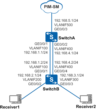
As shown in Figure 1, the core network is running Protocol Independent Multicast - Sparse Mode (PIM-SM). SwitchA connects to the core network and Layer 3 device SwitchB. SwitchB connects to user network segments and does not run PIM.
A large number of users want to receive video programs in multicast mode. SwitchB transparently transmits all IGMP messages sent from user hosts to SwitchA, increasing the loads on SwitchA. This degrades the quality of video programs on user hosts. Loads on SwitchA need to be reduced through appropriate configuration.

In this scenario, to avoid loops, ensure that all connected interfaces have STP disabled and connected interfaces are removed from VLAN 1. If STP is enabled and VLANIF interfaces of switches are used to construct a Layer 3 ring network, an interface on the network will be blocked. As a result, Layer 3 services on the network cannot run normally.
Configuration Roadmap
Configuring IGMP proxy on SwitchB can reduce loads of SwitchA in IGMP message processing. The configuration roadmap is as follows:
To ensure that data sent from multicast sources can be correctly forwarded to the user network segments, configure a unicast routing protocol on the network to implement IP interworking. Multicast routing protocols are dependent on unicast routing protocols.
To enable the switches to forward video streams to the hosts in multicast mode, configure basic multicast functions on the switches.
To allow SwitchB to work as a proxy device between SwitchA and downstream hosts, configure IGMP proxy on VLANIF100 of SwitchB and enable IGMP on its interfaces connected to user network segments.
To prevent service interruption caused by failures the upstream IGMP proxy interface, configure VLANIF400 of SwitchB as the backup IGMP proxy interface.
To ensure validity of (S, G) entries, configure an appropriate multicast source lifetime on SwitchB.
Procedure
- Configure IP addresses for router interfaces and configure
a unicast routing protocol on the routers.
# Configure IP addresses and masks for switch interfaces according to Figure 1. Configure Open Shortest Path First (OSPF) on the switches to implement IP interworking and dynamic route update. The configuration of SwitchB is similar to the configuration of SwitchA, and is not mentioned here. See Configuration Files.
<HUAWEI> system-view
[HUAWEI] sysname SwitchA
[SwitchA] vlan batch 100 400 500
[SwitchA] interface gigabitethernet 0/0/1
[SwitchA-GigabitEthernet0/0/1] port link-type trunk
[SwitchA-GigabitEthernet0/0/1] port trunk allow-pass vlan 100
[SwitchA-GigabitEthernet0/0/1] quit
[SwitchA] interface gigabitethernet 0/0/2
[SwitchA-GigabitEthernet0/0/2] port link-type trunk
[SwitchA-GigabitEthernet0/0/2] port trunk allow-pass vlan 400
[SwitchA-GigabitEthernet0/0/2] quit
[SwitchA] interface gigabitethernet 0/0/3
[SwitchA-GigabitEthernet0/0/3] port link-type trunk
[SwitchA-GigabitEthernet0/0/3] port trunk allow-pass vlan 500
[SwitchA-GigabitEthernet0/0/3] quit
[SwitchA] interface vlanif 100
[SwitchA-Vlanif100] ip address 192.168.1.1 24
[SwitchA-Vlanif100] quit
[SwitchA] interface vlanif 400
[SwitchA-Vlanif400] ip address 192.168.4.1 24
[SwitchA-Vlanif400] quit
[SwitchA] interface vlanif 500
[SwitchA-GigabitEthernet3/0/0] ip address 192.168.5.1 24
[SwitchA-GigabitEthernet3/0/0] quit
[SwitchA] ospf
[SwitchA-ospf-1] area 0
[SwitchA-ospf-1-area-0.0.0.0] network 192.168.1.0 0.0.0.255
[SwitchA-ospf-1-area-0.0.0.0] network 192.168.4.0 0.0.0.255
[SwitchA-ospf-1-area-0.0.0.0] network 192.168.5.0 0.0.0.255
[SwitchA-ospf-1-area-0.0.0.0] quit
[SwitchA-ospf-1] quit
- Enable IP multicast routing, PIM-SM, and IGMP on SwitchA.
# On SwitchA, enable IP multicast routing globally and enable PIM-SM on VLANIF500. Configure VLANIF500 as the C-BSR and C-RP.
[SwitchA] multicast routing-enable
[SwitchA] interface vlanif 500
[SwitchA-Vlanif500] pim sm
[SwitchA-Vlanif500] quit
[SwitchA] pim
[SwitchA-pim] c-bsr vlanif 500
[SwitchA-pim] c-rp vlanif 500
[SwitchA-pim] quit
# Enable IGMP on VLANIF100 and VLANIF400 of SwitchA and set the IGMP version to v3.
[SwitchA] interface vlanif 100
[SwitchA-Vlanif100] igmp enable
[SwitchA-Vlanif100] igmp version 3
[SwitchA-Vlanif100] quit
[SwitchA] interface vlanif 400
[SwitchA-Vlanif400] igmp enable
[SwitchA-Vlanif400] igmp version 3
[SwitchA-Vlanif400] quit
- Enable IP multicast routing and IGMP on SwitchB (IGMP proxy
device).
# On SwitchB, enable IP multicast routing globally, enable IGMP on VLANIF200 and VLANIF300, and set the IGMP version to v3.
[SwitchB] multicast routing-enable
[SwitchB] interface vlanif 200
[SwitchB-Vlanif200] igmp enable
[SwitchB-Vlanif200] igmp version 3
[SwitchB-Vlanif200] quit
[SwitchB] interface vlanif 300
[SwitchB-Vlanif300] igmp enable
[SwitchB-Vlanif300] igmp version 3
[SwitchB-Vlanif300] quit
- Enable IGMP proxy on an upstream interface of SwitchB.
# Enable IGMP proxy on VLANIF100 of SwitchB and set the IGMP robustness variable to 3.
[SwitchB] interface vlanif 100
[SwitchB-Vlanif100] igmp proxy
[SwitchB-Vlanif100] igmp version 3
[SwitchB-Vlanif100] igmp robust-count 3
[SwitchB-Vlanif100] quit
- Enable IGMP proxy backup on another upstream interface
of SwitchB.
# Enable IGMP proxy on VLANIF400 of SwitchB.
[SwitchB] interface vlanif 400
[SwitchB-Vlanif400] igmp proxy backup
[SwitchB-Vlanif400] igmp version 3
[SwitchB-Vlanif400] quit
- Configure a multicast source lifetime in the IGMP view
on SwitchB.
# Set the multicast source lifetime to 300 seconds in the IGMP view on SwitchB.
[SwitchB] igmp
[SwitchB-igmp] proxy source-lifetime 300
[SwitchB-igmp] quit
- Verify the IGMP proxy configurations.
# Run the display igmp proxy interface command to check the IGMP proxy interface on SwitchB.
[SwitchB] display igmp proxy interface
Interface information of VPN-Instance: public net
 Vlanif100(192.168.1.2):
   IGMP proxy is enabled
   Current IGMP proxy version (negotiated) is 3
   Current IGMP proxy version (configured) is 3
   IGMP proxy state: up
   Value of query interval for IGMP (negotiated): 60 s
   Value of query interval for IGMP (configured): 60 s
   Value of querier present timeout for IGMPv1: off
   Value of querier present timeout for IGMPv2: off
   Value of querier present timeout for IGMPv3: 124s
   General query response expiry: off
   Querier for IGMP: 192.168.1.1
   Robustness (negotiated): 3
   Robustness (configured): 3
   Require-router-alert: disabled
   Send-router-alert: enabled
   Ip-source-policy: disabled

 Vlanif400(192.168.4.2):
   IGMP proxy backup is enabled
   Current IGMP proxy version (negotiated) is 3
   Current IGMP proxy version (configured) is 3
   IGMP proxy state: up
   Value of query interval for IGMP (negotiated): 60 s
   Value of query interval for IGMP (configured): 60 s
   Value of querier present timeout for IGMPv1: off
   Value of querier present timeout for IGMPv2: off
   Value of querier present timeout for IGMPv3: 124s
   General query response expiry: off
   Querier for IGMP: 192.168.4.1
   Robustness (negotiated): 2
   Robustness (configured): 2
   Require-router-alert: disabled
   Send-router-alert: enabled
   Ip-source-policy: disabled
The command output shows that IGMP proxy is enabled on VLANIF100, and VLANIF400 functions as a backup for VLANIF100.
# Run the display igmp proxy routing-table command to check the IGMP proxy routing table on SwitchB. Receiver1 sent a (10.1.1.1, 232.1.1.1) Report message.
[SwitchB] display igmp proxy routing-table
Routing table of VPN-Instance: public net
 Total 0 (*, G) entry; 1 (S, G) entry

 (10.1.1.1, 232.1.1.1)
     Flag: JOIN, UpTime: 01:38:45
     Upstream interface: Vlanif100
     Downstream interface(s) information:
     Total number of downstreams: 1
         1: Vlanif200
             Protocol: igmp, UpTime: 01:38:45
The command output shows the (10.1.1.1, 232.1.1.1) entry in the IGMP proxy routing table of SwitchB. This indicates that Receiver1 has joined (10.1.1.1, 232.1.1.1).
Configuration Files
SwitchA configuration file
#
 sysname SwitchA
#
vlan batch 100 400 500
#
multicast routing-enable
#
interface Vlanif100
 ip address 192.168.1.1 255.255.255.0
 igmp enable
 igmp version 3
#
interface Vlanif400
 ip address 192.168.4.1 255.255.255.0
 igmp enable
 igmp version 3
#
interface Vlanif500
 ip address 192.168.5.1 255.255.255.0
 pim sm
#
interface GigabitEthernet0/0/1
 port link-type trunk
 port trunk allow-pass vlan 100
#
interface GigabitEthernet0/0/2
 port link-type trunk
 port trunk allow-pass vlan 400
#
interface GigabitEthernet0/0/3
 port link-type trunk
 port trunk allow-pass vlan 500
#
ospf 1
 area 0.0.0.0
  network 192.168.1.0 0.0.0.255
  network 192.168.4.0 0.0.0.255
  network 192.168.5.0 0.0.0.255
#
pim
 c-bsr Vlanif400
 c-rp Vlanif400
#
return
SwitchB configuration file
#
 sysname SwitchB
#
vlan batch 100 200 300 400
#
multicast routing-enable
#
interface Vlanif100
 ip address 192.168.1.2 255.255.255.0
 igmp version 3
 igmp robust-count 3
 igmp proxy
#
interface Vlanif200
 ip address 192.168.2.1 255.255.255.0
 igmp enable
 igmp version 3
#
interface Vlanif300
 ip address 192.168.3.1 255.255.255.0
 igmp enable
 igmp version 3
#
interface Vlanif400
 ip address 192.168.4.2 255.255.255.0
 igmp version 3
 igmp proxy backup
#
interface GigabitEthernet0/0/1
 port link-type trunk
 port trunk allow-pass vlan 100
#
interface GigabitEthernet0/0/2
 port link-type trunk
 port trunk allow-pass vlan 200
#
interface GigabitEthernet0/0/3
 port link-type trunk
 port trunk allow-pass vlan 300
#
interface GigabitEthernet0/0/4
 port link-type trunk
 port trunk allow-pass vlan 400
#
ospf 1
 area 0.0.0.0
  network 192.168.1.0 0.0.0.255
  network 192.168.2.0 0.0.0.255
  network 192.168.3.0 0.0.0.255
  network 192.168.4.0 0.0.0.255
#
igmp
 proxy source-lifetime 300
#
return