Example for Configuring IGMP Snooping in a VSI
Networking Requirements
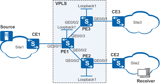
On the virtual private LAN service (VPLS) network shown in Figure 1, PE1 is a superstratum PE (SPE) device; PE2 and PE3 are underlayer PE (UPE) devices. If a virtual switching instance (VSI) on the PE devices does not support IGMP snooping, multicast data packets are broadcast in the VSI. This wastes network resources.
After IGMP snooping is configured in the VSI, multicast data packets are sent only to the devices connected to receiver hosts, conserving network resources.
If the network topology is stable, configure the PW on PE2 as a static router port in the VSI so that receivers can always receive multicast data packets.
Switch |
Interface and IP Address |
|---|---|
PE1 |
|
PE2 |
|
PE3 |
|
Configuration Roadmap
The configuration roadmap is as follows:
Configure basic VPLS functions.
Enable IGMP snooping on the PE devices.
Procedure
- Configure IP address for PE interfaces, and add physical interfaces to specified VLANs.
# Configure PE1. The configurations of PE2 and PE3 are similar to the configuration of PE1, and are not provided here.
<HUAWEI> system-view
[HUAWEI] sysname PE1
[PE1] vlan batch 10 20 40
[PE1] interface gigabitethernet 0/0/1
[PE1-GigabitEthernet0/0/1] port link-type trunk
[PE1-GigabitEthernet0/0/1] port trunk allow-pass vlan 40
[PE1-GigabitEthernet0/0/1] quit
[PE1] interface gigabitethernet 0/0/2
[PE1-GigabitEthernet0/0/2] port link-type trunk
[PE1-GigabitEthernet0/0/2] port trunk allow-pass vlan 10
[PE1-GigabitEthernet0/0/2] quit
[PE1] interface gigabitethernet 0/0/3
[PE1-GigabitEthernet0/0/3] port link-type trunk
[PE1-GigabitEthernet0/0/3] port trunk allow-pass vlan 20
[PE1-GigabitEthernet0/0/3] quit
[PE1] interface vlanif 10
[PE1-Vlanif10] ip address 10.1.1.1 24
[PE1-Vlanif10] quit
[PE1] interface vlanif 20
[PE1-Vlanif20] ip address 10.2.1.1 24
[PE1-Vlanif20] quit
[PE1] interface loopback1
[PE1-LoopBack1] ip address 1.1.1.1 32
[PE1-LoopBack1] quit
- Configure Open Shortest Path First (OSPF) to advertise the network segments connected to VLANIF interfaces and host routes of the label switching router (LSR) IDs.
# Configure PE1. The configurations of PE2 and PE3 are similar to the configuration of PE1, and are not provided here.
[PE1] ospf
[PE1-ospf-1] area 0
[PE1-ospf-1-area-0.0.0.0] network 1.1.1.1 0.0.0.0
[PE1-ospf-1-area-0.0.0.0] network 10.1.1.1 0.0.0.255
[PE1-ospf-1-area-0.0.0.0] network 10.2.1.1 0.0.0.255
[PE1-ospf-1-area-0.0.0.0] quit
[PE1-ospf-1] quit
- Configure basic Multiprotocol Label Switching (MPLS) functions and Label Distribution Protocol (LDP).
# Configure PE1.
[PE1] mpls lsr-id 1.1.1.1
[PE1] mpls
[PE1-mpls] quit
[PE1] mpls ldp
[PE1-mpls-ldp] quit
[PE1] interface vlanif 10
[PE1-Vlanif10] mpls
[PE1-Vlanif10] mpls ldp
[PE1-Vlanif10] quit
[PE1] interface vlanif 20
[PE1-Vlanif20] mpls
[PE1-Vlanif20] mpls ldp
[PE1-Vlanif20] quit
# Configure PE2.
[PE2] mpls lsr-id 2.2.2.2
[PE2] mpls
[PE2-mpls] quit
[PE2] mpls ldp
[PE2-mpls-ldp] quit
[PE2] interface vlanif 10
[PE2-Vlanif10] mpls
[PE2-Vlanif10] mpls ldp
[PE2-Vlanif10] quit
# Configure PE3.
[PE3] mpls lsr-id 3.3.3.3
[PE3] mpls
[PE3-mpls] quit
[PE3] mpls ldp
[PE3-mpls-ldp] quit
[PE3] interface vlanif 20
[PE3-Vanif20] mpls
[PE3-Vanif20] mpls ldp
[PE3-Vanif20] quit
- Establish a remote LDP session between the PE devices.
# Configure PE1.
[PE1] mpls ldp remote-peer 2.2.2.2
[PE1-mpls-ldp-remote-2.2.2.2] remote-ip 2.2.2.2
[PE1-mpls-ldp-remote-2.2.2.2] quit
[PE1] mpls ldp remote-peer 3.3.3.3
[PE1-mpls-ldp-remote-3.3.3.3] remote-ip 3.3.3.3
[PE1-mpls-ldp-remote-3.3.3.3] quit
# Configure PE2.
[PE2] mpls ldp remote-peer 1.1.1.1
[PE2-mpls-ldp-remote-1.1.1.1] remote-ip 1.1.1.1
[PE2-mpls-ldp-remote-1.1.1.1] quit
# Configure PE3.
[PE3] mpls ldp remote-peer 1.1.1.1
[PE3-mpls-ldp-remote-1.1.1.1] remote-ip 1.1.1.1
[PE3-mpls-ldp-remote-1.1.1.1] quit
- Enable MPLS L2VPN and configure a VSI.
# Configure PE1.
[PE1] mpls l2vpn
[PE1-l2vpn] quit
[PE1] vsi v123 static
[PE1-vsi-v123] pwsignal ldp
[PE1-vsi-v123-ldp] vsi-id 123
[PE1-vsi-v123-ldp] peer 2.2.2.2
[PE1-vsi-v123-ldp] peer 3.3.3.3
[PE1-vsi-v123-ldp] quit
[PE1-vsi-v123] quit
# Configure PE2.
[PE2] mpls l2vpn
[PE2-l2vpn] quit
[PE2] vsi v123 static
[PE2-vsi-v123] pwsignal ldp
[PE2-vsi-v123-ldp] vsi-id 123
[PE2-vsi-v123-ldp] peer 1.1.1.1
[PE2-vsi-v123-ldp] quit
[PE2-vsi-v123] quit
# Configure PE3.
[PE3] mpls l2vpn
[PE3-l2vpn] quit
[PE3] vsi v123 static
[PE3-vsi-v123] pwsignal ldp
[PE3-vsi-v123-ldp] vsi-id 123
[PE3-vsi-v123-ldp] peer 1.1.1.1
[PE3-vsi-v123-ldp] quit
[PE3-vsi-v123] quit
- Bind the VSI to PE interfaces.
# Configure PE1.
[PE1] interface vlanif 40
[PE1-Vlanif40] l2 binding vsi v123
[PE1-Vlanif40] quit
# Configure PE2.
[PE2] interface vlanif 50
[PE2-Vlanif50] l2 binding vsi v123
[PE2-Vlanif50] quit
# Configure PE3.
[PE3] interface vlanif 60
[PE3-Vlanif60] l2 binding vsi v123
[PE3-Vlanif60] quit
- Enable IGMP snooping on PE1, PE2, and PE3.
# Configure PE1.
[PE1] igmp-snooping enable
[PE1] igmp-snooping over-vpls enable
[PE1] vsi v123
[PE1-vsi-v123] igmp-snooping enable
[PE1-vsi-v123] quit
# Configure PE2.
[PE2] igmp-snooping enable
[PE2] igmp-snooping over-vpls enable
[PE2] vsi v123
[PE2-vsi-v123] igmp-snooping enable
[PE2-vsi-v123] quit
# Configure PE3.
[PE3] igmp-snooping enable
[PE3] igmp-snooping over-vpls enable
[PE3] vsi v123
[PE3-vsi-v123] igmp-snooping enable
[PE3-vsi-v123] quit
- Configure the pseudo wire (PW) on PE2 as a static router port.
[PE2] vsi v123
[PE2-vsi-v123] igmp-snooping static-router-port remote-peer 1.1.1.1
[PE2-vsi-v123] quit
- Verify the configuration.
Run the display igmp-snooping router-port vsi command on PE2 to check whether the static router port is successfully configured.
[PE2] display igmp-snooping router-port vsi v123
 Port Name                       UpTime        Expires       Flags
 ---------------------------------------------------------------------
 VSI v123, 1 router-port(s)
 PW(1.1.1.1/123)                 00:05:16      --            STATIC
STATIC in the command output indicates that the PW (1.1.1.1/123) has been configured as a static router port.
Configuration Files
PE1 configuration file
#
sysname PE1
#
vlan batch 10 20 40
#
igmp-snooping enable
igmp-snooping over-vpls enable
#
mpls lsr-id 1.1.1.1
mpls
#
mpls l2vpn
#
vsi v123 static
 pwsignal ldp
  vsi-id 123
  peer 2.2.2.2
  peer 3.3.3.3
 igmp-snooping enable
#
mpls ldp
#
mpls ldp remote-peer 2.2.2.2
 remote-ip 2.2.2.2
#
mpls ldp remote-peer 3.3.3.3
 remote-ip 3.3.3.3
#
interface Vlanif10
 ip address 10.1.1.1 255.255.255.0
 mpls
 mpls ldp
#
interface Vlanif20
 ip address 10.2.1.1 255.255.255.0
 mpls
 mpls ldp
#
interface Vlanif40
 l2 binding vsi v123
#
interface GigabitEthernet0/0/1
 port link-type trunk
 port trunk allow-pass vlan 40
#
interface GigabitEthernet0/0/2
 port link-type trunk
 port trunk allow-pass vlan 10
#
interface GigabitEthernet0/0/3
 port link-type trunk
 port trunk allow-pass vlan 20
#
interface LoopBack1
 ip address 1.1.1.1 255.255.255.255
#
ospf 1
 area 0.0.0.0
  network 1.1.1.1 0.0.0.0
  network 10.1.1.0 0.0.0.255
  network 10.2.1.0 0.0.0.255
#
return
PE2 configuration file
#
sysname PE2
#
vlan batch 10 50
#
igmp-snooping enable
igmp-snooping over-vpls enable
#
mpls lsr-id 2.2.2.2
mpls
#
mpls l2vpn
#
vsi v123 static
 pwsignal ldp
  vsi-id 123
  peer 1.1.1.1
 igmp-snooping enable
 igmp-snooping static-router-port remote-peer 1.1.1.1
#
mpls ldp
#
mpls ldp remote-peer 1.1.1.1
 remote-ip 1.1.1.1
#
interface Vlanif10
 ip address 10.1.1.2 255.255.255.0
 mpls
 mpls ldp
#
interface Vlanif50
 l2 binding vsi v123
#
interface GigabitEthernet0/0/1
 port link-type trunk
 port trunk allow-pass vlan 50
#
interface GigabitEthernet0/0/2
 port link-type trunk
 port trunk allow-pass vlan 10
#
interface LoopBack1
 ip address 2.2.2.2 255.255.255.255
#
ospf 1
 area 0.0.0.0
  network 2.2.2.2 0.0.0.0
  network 10.1.1.0 0.0.0.255
#
return
PE3 configuration file
#
sysname PE3
#
vlan batch 20 60
#
igmp-snooping enable
igmp-snooping over-vpls enable
#
mpls lsr-id 3.3.3.3
mpls
#
mpls l2vpn
#
vsi v123 static
 pwsignal ldp
  vsi-id 123
  peer 1.1.1.1
 igmp-snooping enable
#
mpls ldp
#
mpls ldp remote-peer 1.1.1.1
 remote-ip 1.1.1.1
#
interface Vlanif20
 ip address 10.2.1.2 255.255.255.0
 mpls
 mpls ldp
#
interface Vlanif60
 l2 binding vsi v123
#
interface GigabitEthernet0/0/1
 port link-type trunk
 port trunk allow-pass vlan 60
#
interface GigabitEthernet0/0/2
 port link-type trunk
 port trunk allow-pass vlan 20
#
interface LoopBack1
 ip address 3.3.3.3 255.255.255.255
#
ospf 1
 area 0.0.0.0
  network 3.3.3.3 0.0.0.0
  network 10.2.1.0 0.0.0.255
#
return