Example for Configuring iPCA to Implement End-to-End Packet Loss Measurement
Networking Requirements
An enterprise deploys real-time services on the network, such as video conference and voice services. When packet loss on links is lower than 5%, users are unaware of service quality degrading; however, when packet loss is higher than 10%, user experience degrades.
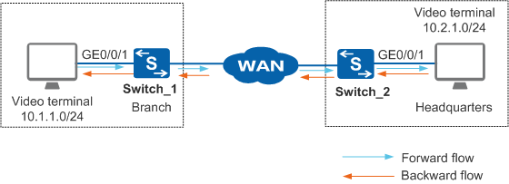
In Figure 1, the users in enterprise branches and headquarters encounter erratic display and delay when using the video conference service. The enterprise wants to obtain packet loss statistics of the video conference service and receive an alarm when the packet loss ratio exceeds 7% so that the network administrator can adjust service deployment in a timely manner.
Configuration Roadmap
Configure a service flow between video terminals as a target flow. It is a bidirectional symmetrical flow, so is divided into two unidirectional flows logically.
Configure Switch_1 as DCP1. Bind GE0/0/1 where the target flow passes to in-point ingress TLP of DCP1. Define instance 1 on DCP1 to collect statistics data of the target flow from TLPs.
Configure Switch_2 as DCP2. Bind GE0/0/1 where the target flow passes to out-point egress TLP of DCP2. Define instance 1 on DCP2 to collect statistics data of the target flow from TLPs.
Configure Switch_2 as the MCP to aggregate statistics data from DCP1 and DCP2 and export the statistics result. Configure packet loss alarm thresholds to help users predict network faults. When the packet loss ratio exceeds 7%, an alarm is reported; when the packet loss ratio falls below 5%, a clear alarm is reported.
Retain the default values of color bit, measurement interval, and UDP port used for communication between DCPs and MCP.

Before configuring iPCA to implement end-to-end packet loss measurement, ensure that the static routes or routing protocols have been configured to implement network connectivity between Switch_1 and Switch_2. The DCP ID or MCP ID of each switch must be an existing IP address, and the IP addresses must be reachable to each other.
Before configuring iPCA to implement end-to-end packet loss measurement, ensure that the NTP protocol has been configured to implement time synchronization between Switch_1 and Switch_2.
Procedure
- Configure Switch_1 as DCP1, set the DCP ID of Switch_1 to the router ID 10.1.1.1, and configure TLP 1.
<HUAWEI> system-view
[HUAWEI] sysname Switch_1
[Switch_1] nqa ipfpm dcp
[Switch_1-nqa-ipfpm-dcp] dcp id 10.1.1.1
[Switch_1-nqa-ipfpm-dcp] instance 1
[Switch_1-nqa-ipfpm-dcp-instance-1] mcp 10.2.1.1
[Switch_1-nqa-ipfpm-dcp-instance-1] flow bidirectional source 10.1.1.0 24 destination 10.2.1.0 24
[Switch_1-nqa-ipfpm-dcp-instance-1] tlp 1 in-point ingress
[Switch_1-nqa-ipfpm-dcp-instance-1] quit
[Switch_1-nqa-ipfpm-dcp] quit
[Switch_1] interface gigabitethernet 0/0/1
[Switch_1-GigabitEthernet0/0/1] ipfpm tlp 1
[Switch_1-GigabitEthernet0/0/1] quit
[Switch_1] nqa ipfpm dcp
[Switch_1-nqa-ipfpm-dcp] instance 1
[Switch_1-nqa-ipfpm-dcp-instance-1] loss-measure enable continual
[Switch_1-nqa-ipfpm-dcp-instance-1] quit
[Switch_1-nqa-ipfpm-dcp] quit
- Configure Switch_2 as DCP2, set the DCP ID of Switch_2 to the router ID 10.2.1.1, and configure TLP 2.
<HUAWEI> system-view
[HUAWEI] sysname Switch_2
[Switch_2] nqa ipfpm dcp
[Switch_2-nqa-ipfpm-dcp] dcp id 10.2.1.1
[Switch_2-nqa-ipfpm-dcp] instance 1
[Switch_2-nqa-ipfpm-dcp-instance-1] mcp 10.2.1.1
[Switch_2-nqa-ipfpm-dcp-instance-1] flow bidirectional source 10.1.1.0 24 destination 10.2.1.0 24
[Switch_2-nqa-ipfpm-dcp-instance-1] tlp 2 out-point egress
[Switch_2-nqa-ipfpm-dcp-instance-1] quit
[Switch_2-nqa-ipfpm-dcp] quit
[Switch_2] interface gigabitethernet 0/0/1
[Switch_2-GigabitEthernet0/0/1] ipfpm tlp 2
[Switch_2-GigabitEthernet0/0/1] quit
[Switch_2] nqa ipfpm dcp
[Switch_2-nqa-ipfpm-dcp] instance 1
[Switch_2-nqa-ipfpm-dcp-instance-1] loss-measure enable continual
[Switch_2-nqa-ipfpm-dcp-instance-1] quit
[Switch_2-nqa-ipfpm-dcp] quit
- Configure Switch_2 as the MCP.
[Switch_2] nqa ipfpm mcp
[Switch_2-nqa-ipfpm-mcp] mcp id 10.2.1.1
[Switch_2-nqa-ipfpm-mcp] instance 1
[Switch_2-nqa-ipfpm-mcp-instance-1] dcp 10.1.1.1
[Switch_2-nqa-ipfpm-mcp-instance-1] dcp 10.2.1.1
[Switch_2-nqa-ipfpm-mcp-instance-1] loss-measure ratio-threshold upper-limit 7 lower-limit 5
[Switch_2-nqa-ipfpm-mcp-instance-1] quit
[Switch_2-nqa-ipfpm-mcp] quit
[Switch_2] quit
- Verify the configuration.
# Run the display ipfpm statistic-type loss instance 1 command on Switch_2 that functions as the MCP to view the packet loss measurement result.
<Switch_2> display ipfpm statistic-type loss instance 1

Latest loss statistics of forward flow:
Unit: p - packet, b - byte
------------------------------------------------------------------------------------------
 Period               Loss(p)              LossRatio(p)  Loss(b)              LossRatio(b)
------------------------------------------------------------------------------------------
 127636768            381549               4.514649%     40444194             4.514649%
 127636767            381528               4.514620%     40441968             4.514620%
 127636766            381318               4.514996%     40419708             4.514996%
 127636765            381192               4.514686%     40406352             4.514686%
 127636764            381381               4.514679%     40426386             4.514679%
 127636763            381402               4.514748%     40428612             4.514748%
 127636762            381081               4.514797%     40394586             4.514797%
 127636761            381324               4.514702%     40420344             4.514702%
 127636760            381549               4.514870%     40444194             4.514870%
 127636759            381066               4.514638%     40392996             4.514638%
 127636758            381570               4.514836%     40446420             4.514836%
 127636757            382452               4.514757%     40539912             4.514757%

Latest loss statistics of backward flow:
Unit: p - packet, b - byte
------------------------------------------------------------------------------------------
 Period               Loss(p)              LossRatio(p)  Loss(b)              LossRatio(b)
------------------------------------------------------------------------------------------
 127636768            381087               4.513306%     40395222             4.513306%
 127636767            381129               4.513384%     40399674             4.513384%
 127636766            381465               4.513444%     40435290             4.513444%
 127636765            381087               4.513222%     40395222             4.513222%
 127636764            381045               4.513272%     40390770             4.513272%
 127636763            381381               4.513364%     40426386             4.513364%
 127636762            381276               4.513435%     40415256             4.513435%
 127636761            380961               4.513280%     40381866             4.513280%
 127636760            381339               4.513574%     40421934             4.513574%
 127636759            381045               4.513270%     40390770             4.513270%
 127636758            381088               4.513226%     40395328             4.513226%
 127636757            382409               4.513464%     40535354             4.513464%
Configuration Files
Switch_1 configuration file
#
sysname Switch_1
#
interface GigabitEthernet0/0/1
 ipfpm tlp 1
#
nqa ipfpm dcp
 dcp id 10.1.1.1
 instance 1
  mcp 10.2.1.1
  flow bidirectional source 10.1.1.0 24 destination 10.2.1.0 24
  tlp 1 in-point ingress
  loss-measure enable continual
#
return
Switch_2 configuration file
#
sysname Switch_2
#
interface GigabitEthernet0/0/1
 ipfpm tlp 2
#
nqa ipfpm dcp
 dcp id 10.2.1.1
 instance 1
  mcp 10.2.1.1
  flow bidirectional source 10.1.1.0 24 destination 10.2.1.0 24
  tlp 2 out-point egress
  loss-measure enable continual
#
nqa ipfpm mcp
 mcp id 10.2.1.1
 instance 1
  dcp 10.1.1.1
  dcp 10.2.1.1
  loss-measure ratio-threshold upper-limit 7.000000 lower-limit 5.000000
#
return