Example for Configuring iPCA to Implement Regional Network Packet Loss Measurement
Networking Requirements
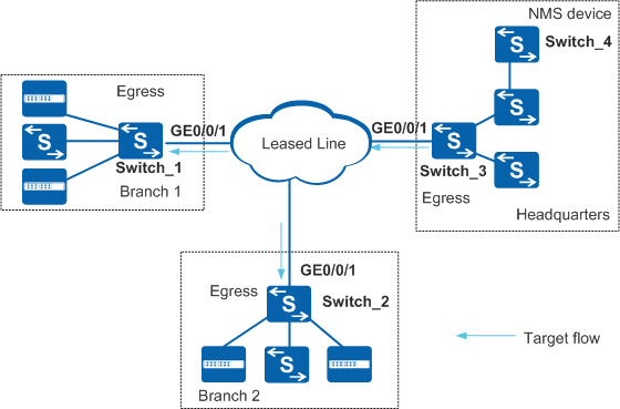
In Figure 1, an enterprise leases the dedicated line from the carrier to transmit important services between headquarters and branches over the WAN. The source address segment is 10.1.1.0/24 and destination address segment is 10.2.0.0/16. The service packets of the enterprise need to pass a large number of public routing and switch devices of the carrier. The enterprise considers the dedicated line not cost-effective, and requires the packet loss data of the WAN to request the carrier to improve service quality.
Configuration Roadmap
Configure the important service flow (source address segment 10.1.1.0/24 and destination address segment 10.2.0.0/16) transmitted over the dedicated line as the target flow. It is a unidirectional service flow.
Configure egress devices Switch_1 and Switch_2 as DCPs. Bind GE0/0/1 where the target flow passes to out-point ingress TLPs of DCPs. Define measurement instance 1 on Switch_1 and Switch_2 to collect statistics data of the target flow from TLPs.
Configure egress device Switch_3 as a DCP. Bind GE0/0/1 where the target flow passes to in-point egress TLP of the DCP. Define instance 1 on Switch_3 to collect statistics data of the target flow from TLPs.
Configure Switch_4 in the headquarters network management center as the MCP to collect the statistics data from DCPs. Configure packet loss alarm and clear alarm thresholds. When the packet loss ratio exceeds 5%, an alarm is reported; when the packet loss ratio falls below 3%, a clear alarm is reported.
Retain the default values of color bit, measurement interval, and UDP port number.

Before configuring iPCA to implement regional network packet loss measurement, ensure that the static routes or routing protocols have been configured to implement network connectivity between Switch_1, Switch_2, Switch_3, and Switch_4. The DCP ID or MCP ID of each switch must be an existing IP address, and the IP addresses must be reachable to each other.
Before configuring iPCA to implement regional network packet loss measurement, ensure that the NTP protocol has been configured to implement time synchronization between Switch_1, Switch_2, and Switch_3.
Procedure
- Configure Switch_1 as DCP1, set the DCP ID of Switch_1 to the router ID 10.10.1.1, and configure TLP 1.
<HUAWEI> system-view
[HUAWEI] sysname Switch_1
[Switch_1] nqa ipfpm dcp
[Switch_1-nqa-ipfpm-dcp] dcp id 10.10.1.1
[Switch_1-nqa-ipfpm-dcp] instance 1
[Switch_1-nqa-ipfpm-dcp-instance-1] mcp 10.10.4.1
[Switch_1-nqa-ipfpm-dcp-instance-1] flow forward source 10.1.1.0 24 destination 10.2.0.0 16
[Switch_1-nqa-ipfpm-dcp-instance-1] tlp 1 out-point ingress
[Switch_1-nqa-ipfpm-dcp-instance-1] quit
[Switch_1-nqa-ipfpm-dcp] quit
[Switch_1] interface gigabitethernet 0/0/1
[Switch_1-GigabitEthernet0/0/1] ipfpm tlp 1
[Switch_1-GigabitEthernet0/0/1] quit
[Switch_1] nqa ipfpm dcp
[Switch_1-nqa-ipfpm-dcp] instance 1
[Switch_1-nqa-ipfpm-dcp-instance-1] loss-measure enable continual
[Switch_1-nqa-ipfpm-dcp-instance-1] quit
[Switch_1-nqa-ipfpm-dcp] quit
- Configure Switch_2 as DCP2, set the DCP ID of Switch_2 to the router ID 10.10.2.1, and configure TLP 2.
<HUAWEI> system-view
[HUAWEI] sysname Switch_2
[Switch_2] nqa ipfpm dcp
[Switch_2-nqa-ipfpm-dcp] dcp id 10.10.2.1
[Switch_2-nqa-ipfpm-dcp] instance 1
[Switch_2-nqa-ipfpm-dcp-instance-1] mcp 10.10.4.1
[Switch_2-nqa-ipfpm-dcp-instance-1] flow forward source 10.1.1.0 24 destination 10.2.0.0 16
[Switch_2-nqa-ipfpm-dcp-instance-1] tlp 2 out-point ingress
[Switch_2-nqa-ipfpm-dcp-instance-1] quit
[Switch_2-nqa-ipfpm-dcp] quit
[Switch_2] interface gigabitethernet 0/0/1
[Switch_2-GigabitEthernet0/0/1] ipfpm tlp 2
[Switch_2-GigabitEthernet0/0/1] quit
[Switch_2] nqa ipfpm dcp
[Switch_2-nqa-ipfpm-dcp] instance 1
[Switch_2-nqa-ipfpm-dcp-instance-1] loss-measure enable continual
[Switch_2-nqa-ipfpm-dcp-instance-1] quit
[Switch_2-nqa-ipfpm-dcp] quit
- Configure Switch_3 as DCP3, set the DCP ID of Switch_3 to the router ID 10.10.3.1, and configure TLP 3.
<HUAWEI> system-view
[HUAWEI] sysname Switch_3
[Switch_3] nqa ipfpm dcp
[Switch_3-nqa-ipfpm-dcp] dcp id 10.10.3.1
[Switch_3-nqa-ipfpm-dcp] instance 1
[Switch_3-nqa-ipfpm-dcp-instance-1] mcp 10.10.4.1
[Switch_3-nqa-ipfpm-dcp-instance-1] flow forward source 10.1.1.0 24 destination 10.2.0.0 16
[Switch_3-nqa-ipfpm-dcp-instance-1] tlp 3 in-point egress
[Switch_3-nqa-ipfpm-dcp-instance-1] quit
[Switch_3-nqa-ipfpm-dcp] quit
[Switch_3] interface gigabitethernet 0/0/1
[Switch_3-GigabitEthernet0/0/1] ipfpm tlp 3
[Switch_3-GigabitEthernet0/0/1] quit
[Switch_3] nqa ipfpm dcp
[Switch_3-nqa-ipfpm-dcp] instance 1
[Switch_3-nqa-ipfpm-dcp-instance-1] loss-measure enable continual
[Switch_3-nqa-ipfpm-dcp-instance-1] quit
[Switch_3-nqa-ipfpm-dcp] quit
- Configure Switch_4 as the MCP and set the MCP ID of Switch_4 to the router ID 10.10.4.1.
<HUAWEI> system-view
[HUAWEI] sysname Switch_4
[Switch_4] nqa ipfpm mcp
[Switch_4-nqa-ipfpm-mcp] mcp id 10.10.4.1
[Switch_4-nqa-ipfpm-mcp] instance 1
[Switch_4-nqa-ipfpm-mcp-instance-1] dcp 10.10.1.1
[Switch_4-nqa-ipfpm-mcp-instance-1] dcp 10.10.2.1
[Switch_4-nqa-ipfpm-mcp-instance-1] dcp 10.10.3.1
[Switch_4-nqa-ipfpm-mcp-instance-1] loss-measure ratio-threshold upper-limit 5 lower-limit 3
[Switch_4-nqa-ipfpm-mcp-instance-1] quit
[Switch_4-nqa-ipfpm-mcp] quit
[Switch_4] quit
- Verify the configuration.
# Run the display ipfpm statistic-type loss instance 1 command on Switch_4 that functions as the MCP to view the packet loss measurement result.
<Switch_4> display ipfpm statistic-type loss instance 1

Latest loss statistics of forward flow:
Unit: p - packet, b - byte
------------------------------------------------------------------------------------------
 Period               Loss(p)              LossRatio(p)  Loss(b)              LossRatio(b)
------------------------------------------------------------------------------------------
 127636768            381549               4.514649%     40444194             4.514649%
 127636767            381528               4.514620%     40441968             4.514620%
 127636766            381318               4.514996%     40419708             4.514996%
 127636765            381192               4.514686%     40406352             4.514686%
 127636764            381381               4.514679%     40426386             4.514679%
 127636763            381402               4.514748%     40428612             4.514748%
 127636762            381081               4.514797%     40394586             4.514797%
 127636761            381324               4.514702%     40420344             4.514702%
 127636760            381549               4.514870%     40444194             4.514870%
 127636759            381066               4.514638%     40392996             4.514638%
 127636758            381570               4.514836%     40446420             4.514836%
 127636757            382452               4.514757%     40539912             4.514757%

Latest loss statistics of backward flow:
Unit: p - packet, b - byte
------------------------------------------------------------------------------------------
 Period               Loss(p)              LossRatio(p)  Loss(b)              LossRatio(b)
------------------------------------------------------------------------------------------
Configuration Files
Switch_1 configuration file
#
sysname Switch_1
#
interface GigabitEthernet0/0/1
 ipfpm tlp 1
#
nqa ipfpm dcp
 dcp id 10.10.1.1
 instance 1
  mcp 10.10.4.1
  flow forward source 10.1.1.0 24 destination 10.2.0.0 16
  tlp 1 out-point ingress
  loss-measure enable continual
#
return
Switch_2 configuration file
#
sysname Switch_2
#
interface GigabitEthernet0/0/1
 ipfpm tlp 2
#
nqa ipfpm dcp
 dcp id 10.10.2.1
 instance 1
  mcp 10.10.4.1
  flow forward source 10.1.1.0 24 destination 10.2.0.0 16
  tlp 2 out-point ingress
  loss-measure enable continual
#
return
Switch_3 configuration file
#
sysname Switch_3
#
interface GigabitEthernet0/0/1
 ipfpm tlp 3
#
nqa ipfpm dcp
 dcp id 10.10.3.1
 instance 1
  mcp 10.10.4.1
  flow forward source 10.1.1.0 24 destination 10.2.0.0 16
  tlp 3 in-point egress
  loss-measure enable continual
#
return
Switch_4 configuration file
#
sysname Switch_4
#
nqa ipfpm mcp
 mcp id 10.10.4.1
 instance 1
  dcp 10.10.1.1
  dcp 10.10.2.1
  dcp 10.10.3.1
  loss-measure ratio-threshold upper-limit 5.000000 lower-limit 3.000000
#
return