Configuring iPCA to Implement Network-Level Hop-by-Hop Packet Loss Measurement
Context
When you detect that packet loss occurs on the network and want to find out the network node where packet loss occurs, you can configure iPCA hop-by-hop packet loss measurement.
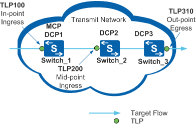
In Figure 1, target flows enter the transit network through Switch_1, pass Switch_2, and leave the network through Switch_3. Configure hop-by-hop packet loss measurement on Switch_1, Switch_2, and Switch_3. When packet loss occurs on the transit network, you can collect packet loss statistics by dividing the network into multiple segments and locate the packet loss points.
Switch_1, Switch_2, and Switch_3 function as DCPs to control and manage TLP 100, TLP 200, and TLP 310, collect packet loss statistics, and send the statistics to the MCP. Switch_1 functions as the MCP to collect packet loss statistics from DCP1, DCP2, and DCP3, summarizes and calculates the statistical data, and reports the statistical results to user terminals or NMS.

There may be iPCA-incapable devices between Switch_1 and Switch_2 and between Switch_2 and Switch_3.
Pre-configuration Tasks
Before configuring iPCA to implement network-level hop-by-hop packet loss measurement, complete the following tasks:
- Configure static routes or routing protocols to ensure network connectivity between devices. For details, see S2720, S5700, and S6700 V200R019C10 Configuration Guide - IP Unicast Routing.
- Configure NTP to implement time synchronization between the devices. For details, see NTP Configuration in the S2720, S5700, and S6700 V200R019C10 Configuration Guide - Device Management.
Configuration Procedure
Configuring the DCP and Configuring the MCP can be configured in any sequence. The parameter settings on MCP and DCPs must be the same.