Example for Configuring iPCA to Implement Hop-by-Hop Packet Loss Measurement
Networking Requirements
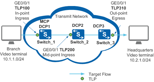
In Figure 1, employees in enterprise branches and headquarters encounter erratic display and delay when participating in a video conference. Network-level end--to-end packet loss measurement has been deployed, and packet loss on the transit network has been detected. To find out where packets are lost in a specified network range, the hop-by-hop packet loss measurement must be configured for the specified service flow.
Configuration Roadmap
Configure hop-by-hop packet loss measurement between Switch_1 and Switch_3 to locate faults on the transit network based on network segments. According to the Atomic Closed Hop (ACH) rule, divide the link between Switch_1 and Switch_3 into two ACHs: ACH1 {TLP 100, TLP 200} and ACH2 {TLP 200, TLP 310}.
Switch_1 functions as the MCP to collect packet loss statistics from DCP1, DCP2, and DCP3, summarize and calculate the statistical data, and report the statistical results to user terminals or NMS.
Configure the IP FPM packet loss alarm threshold and recovery threshold on Switch_1 so that Switch_1 can send alarms to the NMS and notify the NMS of link status in real time.
Switch_1, Switch_2, and Switch_3 function as DCPs to control and manage TLP 100, TLP 200, and TLP 310, collect packet loss statistics, and send the statistics to the MCP.
Retain the default values of the parameters such as UDP port number and authentication methods used by DPCs and MCP.

Before configuring iPCA network-level hop-by-hop packet loss measurement, ensure that the static routes or routing protocols have been configured to implement network connectivity between Switch_1, Switch_2, and Switch_3. The DCP ID or MCP ID of each switch must be an existing IP address, and the IP addresses must be reachable to each other.
Before configuring iPCA to implement regional network packet loss measurement, ensure that the NTP protocol has been configured to implement time synchronization between Switch_1, Switch_2, and Switch_3.
Procedure
- Configure Switch_1 as the MCP and set the MCP ID of Switch_1 to the router ID 10.10.1.1.
<HUAWEI> system-view
[HUAWEI] sysname Switch_1
[Switch_1] nqa ipfpm mcp
[Switch_1-nqa-ipfpm-mcp] mcp id 10.10.1.1
[Switch_1-nqa-ipfpm-mcp] instance 1
[Switch_1-nqa-ipfpm-mcp-instance-1] dcp 10.10.1.1
[Switch_1-nqa-ipfpm-mcp-instance-1] dcp 10.10.2.1
[Switch_1-nqa-ipfpm-mcp-instance-1] dcp 10.10.3.1
[Switch_1-nqa-ipfpm-mcp-instance-1] loss-measure ratio-threshold upper-limit 7 lower-limit 5
[Switch_1-nqa-ipfpm-mcp-instance-1] ach 1
[Switch_1-nqa-ipfpm-mcp-instance-1-ach-1] flow forward
[Switch_1-nqa-ipfpm-mcp-instance-1-ach-1] in-group dcp 10.10.1.1 tlp 100
[Switch_1-nqa-ipfpm-mcp-instance-1-ach-1] out-group dcp 10.10.2.1 tlp 200
[Switch_1-nqa-ipfpm-mcp-instance-1-ach-1] quit
[Switch_1-nqa-ipfpm-mcp-instance-1] ach 2
[Switch_1-nqa-ipfpm-mcp-instance-1-ach-2] flow forward
[Switch_1-nqa-ipfpm-mcp-instance-1-ach-2] in-group dcp 10.10.2.1 tlp 200
[Switch_1-nqa-ipfpm-mcp-instance-1-ach-2] out-group dcp 10.10.3.1 tlp 310
[Switch_1-nqa-ipfpm-mcp-instance-1-ach-2] quit
[Switch_1-nqa-ipfpm-mcp-instance-1] quit
[Switch_1-nqa-ipfpm-mcp] quit
- Configure Switch_1 as DCP1 and configure TLP 100 on it.
[Switch_1] nqa ipfpm dcp
[Switch_1-nqa-ipfpm-dcp] dcp id 10.10.1.1
[Switch_1-nqa-ipfpm-dcp] instance 1
[Switch_1-nqa-ipfpm-dcp-instance-1] mcp 10.10.1.1
[Switch_1-nqa-ipfpm-dcp-instance-1] flow forward source 10.1.1.0 24 destination 10.2.1.0 24
[Switch_1-nqa-ipfpm-dcp-instance-1] tlp 100 in-point ingress
[Switch_1-nqa-ipfpm-dcp-instance-1] quit
[Switch_1-nqa-ipfpm-dcp] quit
[Switch_1] interface gigabitethernet 0/0/1
[Switch_1-GigabitEthernet0/0/1] ipfpm tlp 100
[Switch_1-GigabitEthernet0/0/1] quit
[Switch_1] nqa ipfpm dcp
[Switch_1-nqa-ipfpm-dcp] instance 1
[Switch_1-nqa-ipfpm-dcp-instance-1] loss-measure enable time-range 30
[Switch_1-nqa-ipfpm-dcp-instance-1] quit
[Switch_1-nqa-ipfpm-dcp] quit
[Switch_1] quit
- Configure Switch_2 as DCP2, set the DCP ID of Switch to the router ID 10.10.2.1, and configure TLP 200.
<HUAWEI> system-view
[HUAWEI] sysname Switch_2
[Switch_2] nqa ipfpm dcp
[Switch_2-nqa-ipfpm-dcp] dcp id 10.10.2.1
[Switch_2-nqa-ipfpm-dcp] instance 1
[Switch_2-nqa-ipfpm-dcp-instance-1] mcp 10.10.1.1
[Switch_2-nqa-ipfpm-dcp-instance-1] flow forward source 10.1.1.0 24 destination 10.2.1.0 24
[Switch_2-nqa-ipfpm-dcp-instance-1] tlp 200 mid-point flow forward ingress
[Switch_2-nqa-ipfpm-dcp-instance-1] quit
[Switch_2-nqa-ipfpm-dcp] quit
[Switch_2] interface gigabitethernet 0/0/1
[Switch_2-GigabitEthernet0/0/1] ipfpm tlp 200
[Switch_2-GigabitEthernet0/0/1] quit
[Switch_2] nqa ipfpm dcp
[Switch_2-nqa-ipfpm-dcp] instance 1
[Switch_2-nqa-ipfpm-dcp-instance-1] loss-measure enable mid-point time-range 30
[Switch_2-nqa-ipfpm-dcp-instance-1] quit
[Switch_2-nqa-ipfpm-dcp] quit
- Configure Switch_3 as DCP3, set the DCP ID of Switch_3 to the router ID 10.10.3.1, and configure TLP 310.
<HUAWEI> system-view
[HUAWEI] sysname Switch_3
[Switch_3] nqa ipfpm dcp
[Switch_3-nqa-ipfpm-dcp] dcp id 10.10.3.1
[Switch_3-nqa-ipfpm-dcp] instance 1
[Switch_3-nqa-ipfpm-dcp-instance-1] mcp 10.10.1.1
[Switch_3-nqa-ipfpm-dcp-instance-1] flow forward source 10.1.1.0 24 destination 10.2.1.0 24
[Switch_3-nqa-ipfpm-dcp-instance-1] tlp 310 out-point egress
[Switch_3-nqa-ipfpm-dcp-instance-1] quit
[Switch_3-nqa-ipfpm-dcp] quit
[Switch_3] interface gigabitethernet 0/0/1
[Switch_3-GigabitEthernet0/0/1] ipfpm tlp 310
[Switch_3-GigabitEthernet0/0/1] quit
[Switch_3] nqa ipfpm dcp
[Switch_3-nqa-ipfpm-dcp] instance 1
[Switch_3-nqa-ipfpm-dcp-instance-1] loss-measure enable time-range 30
[Switch_3-nqa-ipfpm-dcp-instance-1] quit
[Switch_3-nqa-ipfpm-dcp] quit
- Verify the configuration.
# Run the display ipfpm statistic-type loss instance 1 ach 1 and display ipfpm statistic-type loss instance 1 ach 2 commands on Switch_1 that functions as the MCP to view the packet loss measurement result.
ach 1 is used as an example here. The values of Loss and LossRatio show whether packet loss occurs on ach 1.
<Switch_1> display ipfpm statistic-type loss instance 1 ach 1

Latest loss statistics of forward flow:
Unit: p - packet, b - byte
------------------------------------------------------------------------------------------
 Period               Loss(p)              LossRatio(p)  Loss(b)              LossRatio(b)
------------------------------------------------------------------------------------------
 136190088            10                   10.000000%    1000                 10.000000%
 136190087            10                   12.000000%    1000                 12.000000%
 136190086            10                   10.000000%    1000                 10.000000%
 136190085            10                   12.000000%    1000                 12.000000%
 136190084            10                   10.000000%    1000                 10.000000%
 136190083            10                   11.000000%    1000                 11.000000%
 136190082            10                   10.000000%    1000                 10.000000%

Latest loss statistics of backward flow:
Unit: p - packet, b - byte
------------------------------------------------------------------------------------------
 Period               Loss(p)              LossRatio(p)  Loss(b)              LossRatio(b)
------------------------------------------------------------------------------------------
Configuration Files
Switch_1 configuration file
#
sysname Switch_1
#
interface GigabitEthernet0/0/1
 ipfpm tlp 100
#
nqa ipfpm dcp
 dcp id 10.10.1.1
 instance 1
  mcp 10.10.1.1
  flow forward source 10.1.1.0 24 destination 10.2.1.0 24
  tlp 100 in-point ingress
#
nqa ipfpm mcp
 mcp id 10.10.1.1
 instance 1
  dcp 10.10.1.1
  dcp 10.10.2.1
  dcp 10.10.3.1
  loss-measure ratio-threshold upper-limit 7.000000 lower-limit 5.000000
  ach 1
   flow forward
   in-group dcp 10.10.1.1 tlp 100
   out-group dcp 10.10.2.1 tlp 200
  ach 2
   flow forward
   in-group dcp 10.10.2.1 tlp 200
   out-group dcp 10.10.3.1 tlp 310
#
return
Switch_2 configuration file
#
sysname Switch_2
#
interface GigabitEthernet0/0/1
 ipfpm tlp 200
#
nqa ipfpm dcp
 dcp id 10.10.2.1
 instance 1
  mcp 10.10.1.1
  flow forward source 10.1.1.0 24 destination 10.2.1.0 24
  tlp 200 mid-point flow forward ingress
#
return
Switch_3 configuration file
#
sysname Switch_3
#
interface GigabitEthernet0/0/1
 ipfpm tlp 310
#
nqa ipfpm dcp
 dcp id 10.10.3.1
 instance 1
  mcp 10.10.1.1
  flow forward source 10.1.1.0 24 destination 10.2.1.0 24
  tlp 310 out-point egress
#
return