Example for Establishing an IPSec Tunnel Using an Efficient VPN Policy in Client Mode
Networking Requirements
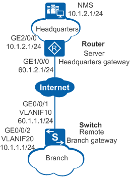
As shown in Figure 1, Switch (remote small-scale branch gateway) and Router (headquarters gateway) communicate through the Internet. The headquarters and branch networks are not planned uniformly.
The enterprise requires that traffic between headquarters and branch networks be securely transmitted and the headquarters gateway manage the branch gateway with simplified configuration in centralized manner through a network management system (NMS). An Efficient VPN policy in client mode can be used to establish an IPSec tunnel to protect traffic. This method facilitates IPSec tunnel establishment and maintenance.
In client mode, Switch requests an IP address from Router to establish an IPSec tunnel, and requests the DNS domain name, DNS server IP addresses, and WINS server IP addresses for the branch.

Huawei S series switches can only function as the remote end of an Efficient VPN. In this configuration example, an AR3200 series router serves as the Efficient VPN server, and the configurations of the AR3260 V200R008 are used for reference. On a live network, select a proper Efficient VPN server based on site requirements and complete the configurations on it according to the product manual.
VLANIF10 on the branch gateway obtains an IP address through DHCP. In this example, we assume that the obtained IP address is 60.1.1.1.
Configuration Roadmap
The configuration roadmap is as follows:
Configure IP addresses and static routes for interfaces on Switch and Router so that routes between Switch and Router are reachable.
Configure Router as the responder to use an IPSec policy template to establish an IPSec tunnel with Switch.
On Router, configure the resources to be allocated, including the IP address, DNS domain name, DNS server IP addresses, and WINS server IP addresses.
Configure an Efficient VPN policy in client mode on Switch. Switch as the initiator establishes an IPSec tunnel with Router.
Procedure
- Configure IP addresses and static routes for interfaces.
# Assign an IP address to an interface on Switch.
<HUAWEI> system-view
[HUAWEI] sysname Switch
[Switch] vlan batch 10 20
[Switch] interface gigabitethernet 0/0/1
[Switch-GigabitEthernet0/0/1] port link-type trunk
[Switch-GigabitEthernet0/0/1] port trunk allow-pass vlan 10
[Switch-GigabitEthernet0/0/1] quit
[Switch] interface gigabitethernet 0/0/2
[Switch-GigabitEthernet0/0/2] port link-type trunk
[Switch-GigabitEthernet0/0/2] port trunk allow-pass vlan 20
[Switch-GigabitEthernet0/0/2] quit
[Switch] interface vlanif 10
[Switch-Vlanif10] ip address dhcp-alloc
[Switch-Vlanif10] quit
[Switch] interface vlanif 20
[Switch-Vlanif20] ip address 10.1.1.1 255.255.255.0
[Switch-Vlanif20] quit
# Configure a static route to the peer on Switch. This example assumes that the next hop address in the route to Router is 60.1.1.2.
[Switch] ip route-static 0.0.0.0 0.0.0.0 60.1.1.2# Assign an IP address to an interface on Router.
<HUAWEI> system-view
[HUAWEI] sysname Router
[Router] interface gigabitethernet 1/0/0
[Router-GigabitEthernet1/0/0] ip address 60.1.2.1 255.255.255.0
[Router-GigabitEthernet1/0/0] quit
[Router] interface gigabitethernet 2/0/0
[Router-GigabitEthernet2/0/0] ip address 10.1.2.1 255.255.255.0
[Router-GigabitEthernet2/0/0] quit
# Configure a static route to the peer on Router. This example assumes that the next hop address in the route to Switchis 60.1.2.2.
[Router] ip route-static 60.1.1.0 255.255.255.0 60.1.2.2
[Router] ip route-static 10.1.1.0 255.255.255.0 60.1.2.2
[Router] ip route-static 100.1.1.0 255.255.255.0 60.1.2.2
- Configure Router as the responder to use an IPSec policy template to establish an IPSec tunnel with Switch.
# Configure the resources to be allocated, including the IP address, DNS domain name, DNS server IP addresses, and WINS server IP addresses.
[Router] ip pool po1
[Router-ip-pool-po1] network 100.1.1.0 mask 255.255.255.128
[Router-ip-pool-po1] gateway-list 100.1.1.1
[Router-ip-pool-po1] quit
[Router] aaa
[Router-aaa] service-scheme schemetest
[Router-aaa-service-schemetest] ip-pool po1
[Router-aaa-service-schemetest] dns-name mydomain.com.cn
[Router-aaa-service-schemetest] dns 2.2.2.2
[Router-aaa-service-schemetest] dns 2.2.2.3 secondary
[Router-aaa-service-schemetest] wins 3.3.3.2
[Router-aaa-service-schemetest] wins 3.3.3.3 secondary
[Router-aaa-service-schemetest] quit
[Router-aaa] quit
# Configure an IKE proposal and an IKE peer, and bind the service scheme to the IKE peer.
[Router] ike proposal 5
[Router-ike-proposal-5] dh group14
[Router-ike-proposal-5] authentication-algorithm sha2-256
[Router-ike-proposal-5] encryption-algorithm aes-128
[Router-ike-proposal-5] quit
[Router] ike peer rut3
[Router-ike-peer-rut3] undo version 2
[Router-ike-peer-rut3] pre-shared-key cipher huawei@123
[Router-ike-peer-rut3] ike-proposal 5
[Router-ike-peer-rut3] service-scheme schemetest
[Router-ike-peer-rut3] quit
# Configure an IPSec proposal and establish an IPSec policy using an IPSec policy template.
[Router] ipsec proposal prop1
[Router-ipsec-proposal-prop1] esp authentication-algorithm sha2-256
[Router-ipsec-proposal-prop1] esp encryption-algorithm aes 128
[Router-ipsec-proposal-prop1] quit
[Router] ipsec policy-template temp1 10
[Router-ipsec-policy-templet-temp1-10] ike-peer rut3
[Router-ipsec-policy-templet-temp1-10] proposal prop1
[Router-ipsec-policy-templet-temp1-10] quit
[Router] ipsec policy policy1 10 isakmp template temp1
# Apply the IPSec policy to an interface.
[Router] interface gigabitethernet 1/0/0
[Router-GigabitEthernet1/0/0] ipsec policy policy1
[Router-GigabitEthernet1/0/0] quit
- Configure an Efficient VPN policy in client mode on Switch to establish an IPSec tunnel.
# Configure an Efficient VPN policy in client mode and specify the remote address and pre-shared key.
[Switch] ipsec efficient-vpn evpn mode client
[Switch-ipsec-efficient-vpn-evpn] remote-address 60.1.2.1 v1
[Switch-ipsec-efficient-vpn-evpn] pre-shared-key cipher huawei@123
[Switch-ipsec-efficient-vpn-evpn] dh group14
[Switch-ipsec-efficient-vpn-evpn] quit
# Apply the Efficient VPN policy to the interface.
[Switch] interface vlanif 10
[Switch-Vlanif10] ipsec efficient-vpn evpn
[Switch-Vlanif10] quit
- Verify the configuration.
# After the configurations are complete, run the display ipsec packet statistics command to view packet statistics when you ping the IP address of the branch gateway from the headquarters gateway.
# Run the display ike sa command on Switch. The following information is displayed:
[Switch] display ike sa
    Conn-ID  Peer            VPN   Flag(s)   Phase   RemoteType  RemoteID
  ------------------------------------------------------------------------------
       26    60.1.2.1        0     RD|ST     v1:2    IP          60.1.2.1
       25    60.1.2.1        0     RD|ST     v1:1    IP          60.1.2.1

   Number of IKE SA : 2
  ------------------------------------------------------------------------------
  Flag Description:
  RD--READY   ST--STAYALIVE   RL--REPLACED   FD--FADING   TO--TIMEOUT
  HRT--HEARTBEAT   LKG--LAST KNOWN GOOD SEQ NO.   BCK--BACKED UP
  M--ACTIVE   S--STANDBY   A--ALONE  NEG--NEGOTIATING
Configuration Files
Configuration file of Switch
#
 sysname Switch
#
vlan batch 10 20
#
ipsec efficient-vpn evpn mode client
 remote-address 60.1.2.1 v1
 pre-shared-key cipher %^%#`[OXA]:r)798<)(J~%z-#<3+XezdN'h<O$IZvadN%^%#
 dh group14
#
interface Vlanif10
 ip address dhcp-alloc
 ipsec efficient-vpn evpn
#
interface Vlanif20
 ip address 10.1.1.1 255.255.255.0
#
interface GigabitEthernet0/0/1
 port link-type trunk
 port trunk allow-pass vlan 10
#
interface GigabitEthernet0/0/2
 port link-type trunk
 port trunk allow-pass vlan 20
#
ip route-static 0.0.0.0 0.0.0.0 60.1.1.2
#
return
Configuration file of Router
#
 sysname Router
#
ipsec proposal prop1
 esp authentication-algorithm sha2-256
 esp encryption-algorithm aes 128
#
ike proposal 5
 encryption-algorithm aes-128
 dh group14
 authentication-algorithm sha2-256
 authentication-method pre-share
 integrity-algorithm hmac-sha2-256
 prf hmac-sha2-256
#
ike peer rut3
 undo version 2
 pre-shared-key cipher %^%#0Y:SO]e%1MLLlY2v\bk~S]LxLau_yPzpUr>C%TO3%^%#
 ike-proposal 5
 service-scheme schemetest
#
ipsec policy-template temp1 10
 ike-peer rut3
 proposal prop1
#
ipsec policy policy1 10 isakmp template temp1
#
ip pool po1
 gateway-list 100.1.1.1
 network 100.1.1.0 mask 255.255.255.128
#
aaa
 service-scheme schemetest
  dns 2.2.2.2
  dns 2.2.2.3 secondary
  ip-pool po1
  wins 3.3.3.2
  wins 3.3.3.3 secondary
  dns-name mydomain.com.cn
#
interface GigabitEthernet1/0/0
 ip address 60.1.2.1 255.255.255.0
 ipsec policy policy1
#
interface GigabitEthernet2/0/0
 ip address 10.1.2.1 255.255.255.0
#
ip route-static 10.1.1.0 255.255.255.0 60.1.2.2
ip route-static 60.1.1.0 255.255.255.0 60.1.2.2
ip route-static 100.1.1.0 255.255.255.0 60.1.2.2
#
return