Configuring IPSG Based on a Dynamic Binding Table
Context
IPSG based on a dynamic binding table filters IP packets received by untrusted interfaces. This prevents malicious hosts from stealing the IP addresses of authorized hosts to access the network without permission. This function is applicable to a LAN where a large number of hosts reside or the hosts obtain IP addresses through DHCP.
Configuration Procedure
Perform the following operations on the switch to which users connect.
Procedure
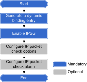
- Create a dynamic binding entry.
Dynamic binding entries include IPv4 and IPv6 entries. Choose one type of entries according to your network type.
If IPv4 or IPv6 hosts on the network obtain IP addresses through DHCP, DHCP snooping can be configured on the switch to generate DHCP snooping dynamic binding entries for the hosts.
- Run the system-view command to enter the system view.
Run the dhcp enable command to enable DHCP.
By default, DHCP is disabled on a switch.
Run the dhcp snooping enable command to enable DHCP snooping globally.
By default, DHCP snooping is disabled globally.
- Enter the VLAN or interface view.
- Run the vlan vlan-id command to enter the VLAN view.
- Run the interface interface-type interface-number command to enter the interface view.
Run the dhcp snooping enable command to enable DHCP snooping in the VLAN or on the interface.
By default, DHCP snooping is disabled in VLANs or on interfaces.
- Configure a trusted interface in either of the following ways:
- Run the dhcp snooping trusted interface interface-type interface-number command in the VLAN view to configure the interfaces in the VLAN as trusted interfaces.
- Run the dhcp snooping trusted command in the interface view to configure the interface as a trusted interface.
By default, a DHCP snooping-enabled interface is untrusted.

Generally, the interface directly or indirectly connected to the DHCP server is configured as a trusted interface. IPSG forwards the IP packets received by the trusted interface without checking them against the binding entry.
For details about the DHCP snooping configuration, see DHCP Snooping Configuration.
If 802.1X authentication is configured on the network, the switch can generate DHCP snooping dynamic binding entries for the hosts that use static IPv4 or IPv6 addresses.
However, these dynamic entries may not be accurate. To address this issue, configure static binding entries for these hosts.
- Run the system-view command to enter the system view.
Run the dhcp enable command to enable DHCP.
By default, DHCP is disabled on a switch.
Run the dhcp snooping enable command to enable DHCP snooping globally.
By default, DHCP snooping is disabled globally.
- Run the interface interface-type interface-number command to enter the interface view.
Run the dhcp snooping enable command to enable DHCP snooping on an interface.
By default, DHCP snooping is disabled on an interface.
Run the dot1x trigger dhcp-binding command (common mode) or dot1x trigger dhcp-binding command (unified mode) to configure the switch to automatically generate DHCP snooping binding entries after hosts using static IP addresses pass 802.1X authentication.
Before performing this configuration in common mode, ensure that 802.1X authentication has been enabled globally and on an interface using the dot1x enable command.
By default, the switch does not generate DHCP snooping binding entries after hosts using static IP addresses pass 802.1X authentication.
For details about the 802.1X authentication configuration, see NAC Configuration (Common Mode) or NAC Configuration (Unified Mode) in the S2720, S5700, and S6700 V200R019C10 Configuration Guide - User Access and Authentication.
- If the network contains IPv6 hosts, you can configure ND snooping on the switch to generate ND snooping dynamic binding entries.
- Run the system-view command to enter the system view.
Run the nd snooping enable command to enable ND snooping globally.
By default, ND snooping is disabled globally.
- Enter the VLAN or interface view.
- Run the vlan vlan-id command to enter the VLAN view.
- Run the interface interface-type interface-number command to enter the interface view.
Run the nd snooping enable command to enable ND snooping in the VLAN or on the interface.
By default, ND snooping is disabled in VLANs or on interfaces.
- Configure a trusted interface in either of the following ways:
- Run the nd snooping trusted interface interface-type interface-number command in the VLAN view to configure the interfaces in the VLAN as ND snooping trusted interfaces.
- Run the nd snooping trusted command in the interface view to configure the interface as an ND snooping trusted interface.
By default, an ND snooping-enabled interface is untrusted.
For details about the ND snooping configuration, see Configuring ND Snooping.
- Enable IPSG.
IPSG does not take effect immediately after a binding entry is created. IPSG takes effect only after it is enabled on the specified interface (user-side interface) or VLAN. There are two ways to enable IPSG.
Enabling IPSG on an interface: IPSG checks all packets received by the interface against the binding entry. Choose this method if you need to check IP packets on the specified interfaces and trust other interfaces. This method is ideal if an interface belongs to multiple VLANs because you do not need to enable IPSG in each VLAN.
Enabling IPSG in a VLAN: IPSG checks the packets received by all interfaces in the VLAN against the binding entry. Choose this method if you need to check IP packets in the specified VLANs and trust other VLANs. This method is ideal if multiple interfaces belong to the same VLAN because you do not need to enable IPSG on each interface.
- If IPSG is enabled on an interface, IPSG takes effect only on this interface, and the switch does not perform an IPSG check on other interfaces.
- If IPSG is enabled in a VLAN, IPSG takes effect only in this VLAN, and the switch does not perform an IPSG check in other VLANs.
- If the device has insufficient ACL resources, the binding entry may fail to be created. However, you can still view IPSG configurations on the device using the display dhcp snooping user-bind { { interface interface-type interface-number | ip-address ip-address | mac-address mac-address | vlan vlan-id } * | all } verbose command. In the command output, check the IPSG Status field to determine whether IPSG is effective.
- Enter the interface or VLAN view.
- Run the interface interface-type interface-number command to enter the interface view.
- Run the vlan vlan-id command to enter the VLAN view.
- Run the ip source check user-bind enable, ipv4 source check user-bind enable, or ipv6 source check user-bind enable command to enable IP packet check on the interface or in the VLAN.
By default, IP packet check is disabled on interfaces or in VLANs.
- (Optional) Configure the IP packet check options.
- If IPSG has been enabled in a VLAN, run the ip source check user-bind check-item { ip-address | mac-address | interface } * command in the VLAN view to configure the IP packet check options.
- If IPSG has been enabled on an interface, run the ip source check user-bind check-item { ip-address | mac-address | vlan } * command in the interface view to configure the IP packet check options.
By default, the IP packet check options include IP address, MAC address, VLAN, and interface. Perform this step if some options are trustable or variable (for example, the inbound interface varies in the scenario where packets from hosts may be received by different interfaces). The default values are recommended.
- (Optional) Configure IP packet check alarm.
This step is valid only when IPSG is enabled on an interface in Step 2. After this alarm function is configured, the switch generates an alarm if the number of discarded IP packets exceeds the threshold.
Run the system-view command to enter the system view.
Run the interface interface-type interface-number command to enter the interface view.
Run the ip source check user-bind alarm enable command to enable the IP packet check alarm.
By default, IP packet check alarm is disabled.
Run the ip source check user-bind alarm threshold threshold command to set the IP packet check alarm threshold.
By default, the IP packet check alarm threshold is 100.
Verifying the Configuration
View the IPSG configuration on an interface.
Run the display ip source check user-bind interface interface-type interface-number command to check the IPSG configuration on the interface.
View the dynamic binding entries and status.
- Run the display dhcp snooping user-bind { { interface interface-type interface-number | ip-address ip-address | mac-address mac-address | vlan vlan-id } * | all } [ verbose ] command to view DHCP snooping dynamic binding entries.
- Run the display dhcpv6 snooping user-bind { { interface interface-type interface-number | ipv6-address { ipv6-address | all } | mac-address mac-address | vlan vlan-id } * | all } [ verbose ] command to view DHCPv6 snooping dynamic binding entries.
- Run the display nd snooping user-bind all [ verbose ] or display nd snooping user-bind { ipv6-address ipv6-address | mac-address mac-address | interface interface-type interface-number | vlan vlan-id } * [ verbose ] command to view ND snooping dynamic binding entries.
You can view the IPSG status by specifying the verbose parameter.- If the value of IPSG Status is IPv4 effective or IPv6 effective, IPSG of this entry takes effect.
- If the value of IPSG Status is ineffective, IPSG of this entry does not take effect. This may be because hardware ACL resources are insufficient.