Example for Configuring a Manual IPv6 over IPv4 Tunnel
Networking Requirements
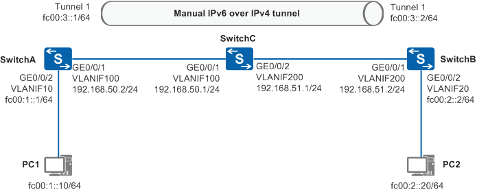
As shown in Figure 1, PC1 and PC2 on two IPv6 networks are connected to SwitchB on an IPv4 backbone network through SwitchA and SwitchC, respectively. A manual IPv6 over IPv4 tunnel needs to be set up between SwitchA and SwitchC so that PC1 and PC2 on the two IPv6 networks can communicate.
Configuration Roadmap
The configuration roadmap is as follows:
Configure the IPv4 backbone network. Configure IP addresses for interfaces so that SwitchA, SwitchB, and SwitchC can communicate on the IPv4 backbone network.
Configure IPv6 networks. Configure IPv6 addresses for the devices at both ends of a manual IPv6 over IPv4 tunnel (that is, SwitchA and SwitchC) so that SwitchA and SwitchC can communicate with PC1 and PC2 on the two IPv6 networks.
Configure a manual IPv6 over IPv4 tunnel. Configure IPv6 addresses, protocol types, source interfaces, and destination addresses for tunnel interfaces so that IPv6 packets can be forwarded on the IPv4 backbone network.
Configure a static route directing IPv6 packets to the manual IPv6 over IPv4 tunnel.
Procedure
- Configure the IPv4 backbone network.
# Configure SwitchA.
<HUAWEI> system-view
[HUAWEI] sysname SwitchA
[SwitchA] vlan batch 100
[SwitchA] interface gigabitethernet 0/0/1
[SwitchA-GigabitEthernet0/0/1] port link-type hybrid
[SwitchA-GigabitEthernet0/0/1] port hybrid pvid vlan 100
[SwitchA-GigabitEthernet0/0/1] port hybrid untagged vlan 100
[SwitchA-GigabitEthernet0/0/1] quit
[SwitchA] interface vlanif 100
[SwitchA-Vlanif100] ip address 192.168.50.2 255.255.255.0
[SwitchA-Vlanif100] quit
[SwitchA] ip route-static 192.168.51.2 255.255.255.0 192.168.50.1
# Configure SwitchB.
<HUAWEI> system-view
[HUAWEI] sysname SwitchB
[SwitchB] vlan batch 100 200
[SwitchB] interface gigabitethernet 0/0/1
[SwitchB-GigabitEthernet0/0/1] port link-type hybrid
[SwitchB-GigabitEthernet0/0/1] port hybrid pvid vlan 100
[SwitchB-GigabitEthernet0/0/1] port hybrid untagged vlan 100
[SwitchB-GigabitEthernet0/0/1] quit
[SwitchB] interface gigabitethernet 0/0/2
[SwitchB-GigabitEthernet0/0/2] port link-type hybrid
[SwitchB-GigabitEthernet0/0/2] port hybrid pvid vlan 200
[SwitchB-GigabitEthernet0/0/2] port hybrid untagged vlan 200
[SwitchB-GigabitEthernet0/0/2] quit
[SwitchB] interface vlanif 100
[SwitchB-Vlanif100] ip address 192.168.50.1 255.255.255.0
[SwitchB-Vlanif100] quit
[SwitchB] interface vlanif 200
[SwitchB-Vlanif200] ip address 192.168.51.1 255.255.255.0
[SwitchB-Vlanif200] quit
# Configure SwitchC.
<HUAWEI> system-view
[HUAWEI] sysname SwitchC
[SwitchC] vlan batch 200
[SwitchC] interface gigabitethernet0/0/1
[SwitchC-GigabitEthernet0/0/1] port link-type hybrid
[SwitchC-GigabitEthernet0/0/1] port hybrid pvid vlan 200
[SwitchC-GigabitEthernet0/0/1] port hybrid untagged vlan 200
[SwitchC-GigabitEthernet0/0/1] quit
[SwitchC] interface vlanif 200
[SwitchC-Vlanif200] ip address 192.168.51.2 255.255.255.0
[SwitchC-Vlanif200] quit
[SwitchC] ip route-static 192.168.50.2 255.255.255.0 192.168.51.1
- Configure IPv6 networks.
# Configure SwitchA.
[SwitchA] ipv6
[SwitchA] vlan batch 10
[SwitchA] interface gigabitethernet 0/0/2
[SwitchA-GigabitEthernet0/0/2] port link-type access
[SwitchA-GigabitEthernet0/0/2] port default vlan 10
[SwitchA-GigabitEthernet0/0/2] quit
[SwitchA] interface vlanif 10
[SwitchA-Vlanif10] ipv6 enable
[SwitchA-Vlanif10] ipv6 address fc00:1::1 64
[SwitchA-Vlanif10] quit
# Configure SwitchC.
[SwitchC] ipv6
[SwitchC] vlan batch 20
[SwitchC] interface gigabitethernet 0/0/2
[SwitchC-GigabitEthernet0/0/2] port link-type access
[SwitchC-GigabitEthernet0/0/2] port default vlan 20
[SwitchC-GigabitEthernet0/0/2] quit
[SwitchC] interface vlanif 20
[SwitchC-Vlanif20] ipv6 enable
[SwitchC-Vlanif20] ipv6 address fc00:2::2 64
[SwitchC-Vlanif20] quit
# Configure PC1 and PC2 on the two IPv6 networks.
Configure the IPv6 addresses of PC1 and PC2 to fc00:1::10/64 and fc00:2::20/64, respectively. Configure the gateway IPv6 addresses of PC1 and PC2 to fc00:1::1 and fc00:2::2, respectively.
- Configure a manual IPv6 over IPv4 tunnel.# Enable the service loopback function on an Eth-Trunk on SwitchA and SwitchC. The following uses SwitchA as an example. The configurations on SwitchC are the same.

The interface must be idle and not transmitting services.
After the service loopback function is enabled on the Eth-Trunk, the physical interface added to the Eth-Trunk must be in the Up state. Otherwise, the link layer protocol of the tunnel interface cannot run properly.
[SwitchA] interface eth-trunk 1
[SwitchA-Eth-Trunk1] service type tunnel
[SwitchA-Eth-Trunk1] quit
[SwitchA] interface gigabitethernet 0/0/3
[SwitchA-GigabitEthernet0/0/3] eth-trunk 1
[SwitchA-GigabitEthernet0/0/3] quit
# Set the tunnel protocol to IPv6-IPv4 on SwitchA and SwitchC. The following uses SwitchA as an example. The configurations on SwitchC are the same.
[SwitchA] interface tunnel 1
[SwitchA-Tunnel1] tunnel-protocol ipv6-ipv4
[SwitchA-Tunnel1] eth-trunk 1
# Configure an IPv6 address and a destination address for the tunnel interface on SwitchA.
[SwitchA-Tunnel1] ipv6 enable
[SwitchA-Tunnel1] ipv6 address fc00:3::1 64
[SwitchA-Tunnel1] source vlanif 100
[SwitchA-Tunnel1] destination 192.168.51.2
[SwitchA-Tunnel1] quit
# Configure an IPv6 address and a destination address for the tunnel interface on SwitchC.
[SwitchC-Tunnel1] ipv6 enable
[SwitchC-Tunnel1] ipv6 address fc00:3::2 64
[SwitchC-Tunnel1] source vlanif 200
[SwitchC-Tunnel1] destination 192.168.50.2
[SwitchC-Tunnel1] quit
- Configure a static route directing IPv6 packets to the manual IPv6 over IPv4 tunnel.
# Configure SwitchA.
[SwitchA] ipv6 route-static fc00:2:: 64 Tunnel 1
# Configure SwitchC.
[SwitchC] ipv6 route-static fc00:1:: 64 Tunnel 1
- Verify the configuration.
# Ping the IPv6 address of PC2 (that is, fc00:2::20) from PC1. PC1 can receive response packets from PC2.
Configuration Files
SwitchA configuration file
#
sysname SwitchA
#
ipv6
#
vlan batch 10 100
#
interface Vlanif10
 ipv6 enable
 ipv6 address FC00:1::1/64
#
interface Vlanif100
 ip address 192.168.50.2 255.255.255.0
#
interface Eth-Trunk1
 service type tunnel
#
interface GigabitEthernet0/0/1
 port link-type hybrid
 port hybrid pvid vlan 100
 port hybrid untagged vlan 100
#
interface GigabitEthernet0/0/2
 port link-type access
 port default vlan 10
#
interface GigabitEthernet0/0/3
 eth-trunk 1
#
interface Tunnel1
 ipv6 enable
 ipv6 address FC00:3::1/64
 tunnel-protocol ipv6-ipv4
 source Vlanif100
 destination 192.168.51.2
 eth-trunk 1
#
ip route-static 192.168.51.0 255.255.255.0 192.168.50.1
#
ipv6 route-static FC00:2:: 64 Tunnel1
#
return
SwitchB configuration file
#
sysname SwitchB
#
vlan batch 100 200
#
interface Vlanif100
 ip address 192.168.50.1 255.255.255.0
#
interface Vlanif200
 ip address 192.168.51.1 255.255.255.0
#
interface GigabitEthernet0/0/1
 port link-type hybrid
 port hybrid pvid vlan 100
 port hybrid untagged vlan 100
#
interface GigabitEthernet0/0/2
 port link-type hybrid
 port hybrid pvid vlan 200
 port hybrid untagged vlan 200
#
return
SwitchC configuration file
#
sysname SwitchC
#
ipv6
#
vlan batch 20 200
#
interface Vlanif20
 ipv6 enable
 ipv6 address FC00:2::2/64
#
interface Vlanif200
 ip address 192.168.51.2 255.255.255.0
#
interface Eth-Trunk1
 service type tunnel
#
interface GigabitEthernet0/0/1
 port link-type hybrid
 port hybrid pvid vlan 200
 port hybrid untagged vlan 200
#
interface GigabitEthernet0/0/2
 port link-type access
 port default vlan 20
#
interface GigabitEthernet0/0/3
 eth-trunk 1
#
interface Tunnel1
 ipv6 enable
 ipv6 address FC00:3::2/64
 tunnel-protocol ipv6-ipv4
 source Vlanif200
 destination 192.168.50.2
 eth-trunk 1
#
ip route-static 192.168.50.0 255.255.255.0 192.168.51.1
#
ipv6 route-static FC00:1:: 64 Tunnel1
#
return
